SENSORS
An essential element of most control systems is the inputs from sensors. Sensors are the components that detect physical changes or events and convert them into
electrical signals to be processed. Sometimes the term transducer is used to refer to the sensor. A transducer is a device that converts one type of energy into another such as mechanical energy to electrical. There are literally hundreds of different types of sensors. A few examples of the most common types follow.
Temperature Sensors
Temperature is probably the most often sensed physical characteristic. Temperature sensors convert temperature to a resistance change or voltage change. The most commonly used temperature sensors are RTDs, thermistors, and thermocouples.
RTD—An RTD is a resistive temperature device. It is essentially just a platinum wire whose resistance varies with temperature. Most of them have a resistance of 100 ohms at zero degrees Celsius (0°C). As the temperature changes, the resistance changes to reflect the change. RTDs have what we call a linear positive temperature coefficient. That is, as the temperature goes up the resistance goes up and vice versa.
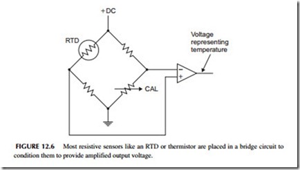
To convert the resistance variation into a voltage, the RTD is usually put into a bridge circuit as shown in Figure 12.6. The bridge is initially balanced with the variable calibrate control (CAL) to produce zero output at a given temperature. Then if the temperature varies, the bridge becomes unbalanced and a voltage is produced. This is then amplified into a larger voltage that is a measure of the temperature. The output can be measured with a meter or it can be digitized for use as in input to a digital system for display or control.
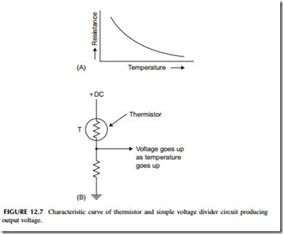
Thermistor—A thermistor is a resistor whose resistance has a negative temperature coefficient. As temperature goes up the resistance goes down and vice versa (see Figure 12.7A ). The resistance change is much greater than that
of an RTD. The thermistor can be used in a simple voltage divider to develop an output voltage or in a bridge circuit like the RTD (see Figure 12.7B).
Thermocouple—A thermocouple is a unique type of temperature sensor, as it develops a voltage rather than a resistance change. It is formed with two dissimilar metals. If the junction of the metals is heated, a voltage is developed. The voltage is usually in the millivolt range so that it usually has to be amplified before it becomes useful. The thermocouple’s main advantage is its accuracy at very high temperatures.
Solid State—Diodes and transistors make good temperature sensors. A silicon diode has a very linear voltage drop variation that decreases with an increase in temperature. This is true of the emitter-base junction of a bipolar transistor as well. Zener regulator diodes exhibit a similar response. The sensor is usually packaged into a complete integrated circuit with an amplifier that produces a voltage output proportional to the temperature variation.
Pressure Sensors
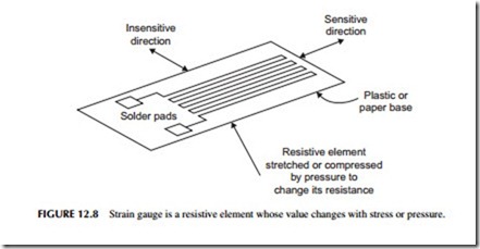
A pressure sensor responds to force or pressure. There are many different types. A widely used kind is called a strain gauge. A strain gauge is essentially a thin pattern of metal deposited on a plastic base like that shown in Figure 12.8. It has a specific value of resistance. A value of 120 ohms is common. The strain
gauge is then glued or cemented with an adhesive to the object to which the pressure is to be applied. An example is a steel beam. When pressure is applied to the beam, it will bend. As it bends, it stretches or compresses the strain gauge resistance element. If the resistive element is stretched, its resistance increases. If it is compressed the resistance decreases. Knowing the specific character- istics of the resistance change per pound of pressure, an exact measure of the pressure can be determined. Mostly strain gauges are used in a bridge circuit like that shown in Figure 12.6. Since the resistance variation is small and the resulting bridge circuit output is small, a special amplifier called an instrumentation amplifier is used. It has differential inputs and very high gain.
A special pressure sensor called a load cell is typically made up of strain gauges. It is fully calibrated to provide a specific voltage output with a specific pressure. Load cells are widely used for weight measurement. An example application is the use of load cells in truck weighing scales.
There are other forms of pressure transducers. Many are solid-state devices with an output voltage proportional to pressure. Piezoelectric pressure transducers use the voltage produced by certain types of crystals or ceramics when pressure is applied to them.
Switches
Switches are widely used as sensors. Switches are mechanical devices with electrical contacts that open or close with a particular physical movement. Switches are used to detect mechanical movement and specifically to deter- mine when the limit of some physical device has been reached. Called limit switches, these devices have various arms and mechanisms that permit ease of use in a variety of situations. Examples of such switches are those that can detect when a cabinet door is open or closed or a switch that senses when a mechanical device reaches a specific point where motion must be stopped.
And of course, a human-operated switch may be the most common. It is usually a button that is pushed to initiate or stop some action.
Potentiometers
A potentiometer is a variable resistor or variable voltage divider. While most electronic pots are rotary devices, they also come in a linear variety. The variable arm of the pot is controlled by some external mechanical device. Then by using the resistance value of the pot or the voltage it produces as a variable voltage divider, it can be used to sense mechanical position.
Photoelectric Sensors
One of the most widely used industrial transducers is a photoelectric sensor. A photoelectric sensor is a component that responds to light and produces an electrical signal that can initiate some operation.
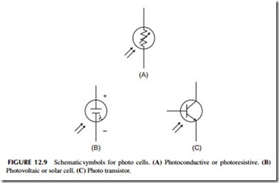
There are three basic types of photoelectric sensors. These are the photo- resistive or photoconductive cell, the photovoltaic cell, and the phototransistor. The photoconductive sensor is a light-sensitive resistor. Its schematic symbol is shown in Figure 12.9A. The resistance of the device varies with the amount of light falling on it. With no light falling on the sensor, its resistance will be very high, 100,000 ohms or more. When bright light shines on the sensor, how- ever, its resistance will drop to a very low value, usually several hundred ohms or less. Of course, at a light level between bright and dark, the resistance of the device will be somewhere between 100 ohms and several hundred thousand ohms. The resistance is inversely proportional to the light level.
Another type of photoelectric device is the photovoltaic cell, whose schematic symbol is illustrated in Figure 12.9B. This is the solar cell described in an earlier chapter. Whenever bright light falls on the cell, it will generate a small DC voltage. The maximum output of a typical photovoltaic cell is approximately 0.45 to 0.5 volt. At lower light levels, the output voltage will be less. Photovoltaic cells are used primarily in power generation systems for producing charging voltage for batteries in satellites and other remote systems. Multiple cells are connected in various series and parallel combinations to get the desired voltage level and current capacity. In some applications, the photovoltaic cell can be used for industrial control. These are also found in portable calculators. Two AA cells at 1.5 volts each produce 3 volts in series. To generate 3 volts with 0.5- volt solar cells, you would need to connect six in series (6 X 0.5 = 3 volts).
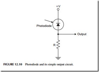
A silicon diode can also be used as a light detector. Special diodes in clear housings are often used to detect light. These are called photodiodes. Photodiodes are operated in the reverse-biased direction, as shown in Figure 12.10. With no light falling on the diode, it is cut off, so there is no voltage across R1. When light strikes the diode, its reverse leakage current increases dramatically, causing a voltage drop to occur across R1.
A phototransistor is a light-sensitive transistor. Its symbol is given in Figure 12.9C. It only has two terminals, the emitter and the collector. The device has a base, but typically it has no lead. Instead, the device is built so that when the base is exposed to light, it will cause the emitter-base junction to conduct. When light strikes the base, it causes ionization, which simulates base-current flow. Therefore, the transistor conducts between emitter and collector. The pri- mary advantage of a phototransistor is its very high sensitivity over a photo- diode. It will conduct even with a small amount of light applied to the base. The transistor essentially provides amplification so that small light levels can control a large current.
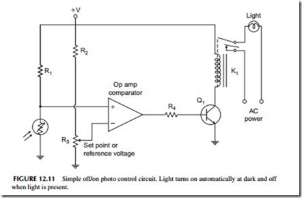
A typical closed-loop control circuit using a photoelectric cell is illustrated in Figure 12.11. This circuit will automatically turn a light on when it gets dark and turn the light off when it is light again. Note that a photoresistive cell is connected as part of a voltage divider with resistor R1. The DC voltage from this voltage divider is applied to one input of an op amp comparator. The DC reference input to the comparator comes from a voltage divider made up of R2 and R3. The potentiometer can be used to adjust the DC reference voltage or set point. The output of the comparator drives a switching transistor Q1, which will turn the relay K1 off or on. This, in turn, operates the light.
When the photoresistive cell is exposed to light, its resistance will be very low. Therefore, the voltage from the voltage divider will be low. It will be less than the DC set point voltage and the comparator will not be triggered. The output of the comparator will be a negative voltage, which will reverse bias the emitter-base junction of the transistor and keep it turned off. As soon as it gets dark outside, the resistance of the photocell will increase. This will cause the voltage-divider output to increase. At some point, the voltage will be higher than the set point voltage, causing the comparator to switch. This applies a positive voltage to the transistor base, turning it on, and then turning on the relay and the light. The light will remain on as long as the photoconductive cell is in the dark. But as soon as light shines on the photocell, the voltage- divider output voltage will drop, thereby triggering the comparator and turning off the transistor, the relay, and the light bulb. By adjusting the reference or set point voltage with potentiometer R3, the triggering point can be varied, so that the light will be turned off or on at the desired level of ambient lighting.
This same basic concept can be used to produce a variety of industrial control operations. For example, you could use the circuit as an entry or intrusion detector. Shine a light on the photocell. If someone or something comes between the light and photocell, the circuit will trigger and the relay could then be used to operate a bell or buzzer or light.
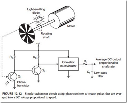
Another example of a photoelectric controller is a tachometer circuit used for measuring the speed of a rotating shaft. Figure 12.12 shows a small, plastic wheel connected to the shaft of a motor. There are alternate clear and opaque areas on the disk. The disk is positioned so that it is between the light-emitting diode (LED) and the phototransistor. As the disk rotates, the dark opaque areas will block the light, while the clear areas pass the light from the LED to the phototransistor. When a clear area on the disk passes, the LED light will shine through it, hitting the phototransistor, and turning it on. When a dark area passes, the light will be blocked and the phototransistor will turn off. The rapidly rotating disk will cause the transistors to turn off and on very rapidly. This rapid conduction and nonconduction of the phototransistor causes a series of pulses to occur at the output of Q2. These pulses are used to trigger the one- shot multivibrator.
The one-shot multivibrator produces a series of fixed, amplitude-width pulses. These are applied to an RC low-pass filter made up of C1 and R1. This filter will average the pulses into a DC voltage. This output voltage is propor- tional to the motor speed. If the speed of the motor should increase, the pulses occur at a more rapid rate. This means that the pulses occur closer together, and thus the average voltage across C1 goes up. A DC voltmeter connected to the output can be used to indicate the speed. At low speeds, the meter indica- tion will be low, while at high speeds it will be high. The meter dial itself can be calibrated in terms of revolutions per minute (rpm), thereby giving an accurate speed indication.
Flow Sensors
These devices have liquid or gas pass through them and measure the amount of flow in gallons per minute or other measure. They develop an output volt- age proportional to flow rate.
There too many other sensors to catalog here but in most cases there is a sensor to convert any physical variable into a voltage to be measured.
