Some Digital Audio Processes Outlined
While digital audio is a large subject, it is not necessarily a difficult one. Every process can be broken down into smaller steps, each of which is relatively easy to assimilate. The main difficulty with study is not following the simple step, but to appreciate where it fits in the overall picture. The next few sections illustrate various important processes in digital audio and show why they are necessary. Such processes are combined in various ways in real equipment.
The Sampler
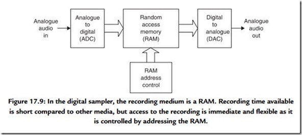
Figure 17.9 consists of an ADC, which is joined to a DAC by way of a quantity of RAM. What the device does is determined by the way in which the RAM address is controlled. If the RAM address increases by one every time a sample from the ADC is stored in the
RAM, a recording can be made for a short period until the RAM is full. The recording can be played back by repeating the address sequence at the same clock rate but reading data from the memory into the DAC. The result is generally called a sampler. By running the replay clock at various rates, the pitch and duration of the reproduced sound can be altered. At a rate of one million bits per second, a megabyte of memory gives only 8 s worth of recording, so clearly samplers will be restricted to a fairly short playing time.
Using data reduction, the playing time of a RAM based recorder can be extended. Some telephone answering machines take messages in RAM and eliminate the cassette tape. For predetermined messages, read only memory can be used instead as it is nonvolatile. Announcements in aircraft, trains, and elevators are one application of such devices.
The Programmable Delay
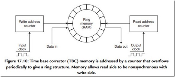
If the RAM of Figure 17.9 is used in a different way, it can be written and read at the same time. The device then becomes an audio delay. Controlling the relationship between the addresses then changes the delay. The addresses are generated by counters that overflow to zero after they have reached a maximum count. As a result the memory space appears to be circular as shown in Figure 17.10. The read and write addresses are driven by a common clock and chase one another around the circle. If the read address follows close behind the write address, the delay is short. If it just stays ahead of the write address, the maximum delay is reached. Programmable delays are useful in TV studios where they allow audio to be aligned with video which has been delayed in
various processes. They can also be used in auditoria to align the sound from various loudspeakers.
In digital audio recorders, a device with a circular memory can be used to remove irregularities from the replay data rate. The off-tape data rate can fluctuate within limits but the output data rate can be held constant. A memory used in this way is called a time base corrector (TBC). All digital recorders have TBCs to eliminate wow and flutter.
Time Compression
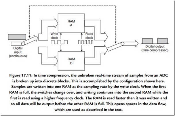
When samples are converted, the ADC must run at a constant clock rate and it outputs an unbroken stream of samples. Time compression allows the sample stream to be broken into blocks for convenient handling.
Figure 17.11 shows an ADC feeding a pair of RAMS. When one is being written by the ADC, the other can be read, and vice versa. As soon as the first RAM is full, the ADC output switched to the input of the other RAM so that there is no loss of samples. The first RAM can then be read at a higher clock rate than the sampling rate. As a result the RAM is read in less time than it took to write it, and the output from the system then pauses until the second RAM is full. The samples are now time compressed. Instead of being an unbroken stream, which is difficult to handle, the samples are now arranged in blocks with convenient pauses in between them. 1n these pauses numerous processes can take place. A rotary head recorder might switch heads; a hard disc might move to another track. On a tape recording, the time compression of the audio samples allows time for synchronizing patterns, subcode, and error-correction words to be recorded.
In digital audio recorders that use video cassette recorders (VCRs), time compression allows the continuous audio samples to be placed in blocks in the unblanked parts of the video waveform, separated by synchronizing pulses.
Subsequently, any time compression can be reversed by time expansion. Samples are written into a RAM at the incoming clock rate, but read out at the standard sampling rate. Unless there is a design fault, time compression is totally inaudible. In a recorder, the time-expansion stage can be combined with the time base-correction stage so that speed variations in the medium can be eliminated at the same time. The use of time compression is universal in digital audio recording. In general the instantaneous data rate at the medium is not the same as the rate at the convertors, although clearly the average rate must be the same.
Another application of time compression is to allow more than one channel of audio to be carried on a single cable. If, for example, audio samples are time compressed by a factor of two, it is possible to carry samples from a stereo source in one cable.
In digital video recorders, both audio and video data are time compressed so that they can share the same heads and tape tracks.
Synchronization
In addition to the analogue inputs and outputs, connected to convertors, many digital recorders have digital inputs that allow the convertors to be bypassed. This mode of connection is desirable because there is no loss of quality in a digital transfer. Transfer of samples between digital audio devices is only possible if both use a common sampling rate and they are synchronized. A digital audio recorder must be able to synchronize to the sampling rate of a digital input in order to record the samples. It is frequently necessary for such a recorder to be able to play back locked to an external sampling rate reference so that it can be connected to, for example, a digital mixer. The process is already common in video systems but now extends to digital audio.
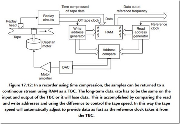
Figure 17.12 shows how the external reference locking process works. The time base expansion is controlled by the external reference, which becomes the read clock for the RAM and so determines the rate at which the RAM address changes. In the case of a digital tape deck, the write clock for the RAM would be proportional to the tape speed. If the tape is going too fast, the write address will catch up with the read address in the memory, whereas if the tape is going too slow the read address will catch up with the write address. The tape speed is controlled by subtracting the read address from the write address. The address difference is used to control the tape speed. Thus if the tape speed is too high, the memory will fill faster than it is being emptied, and the address difference will grow larger than normal. This slows down the tape.
Thus in a digital recorder the speed of the medium is constantly changing to keep the data rate correct. Clearly this is inaudible as properly engineered time base correction totally isolates any instabilities on the medium from data fed to the convertor.
In multitrack recorders, the various tracks can be synchronized to sample accuracy so that no timing errors can exist between the tracks. In stereo recorders image shift due to phase errors is eliminated.
In order to replay without a reference, perhaps to provide an analogue output, a digital recorder generates a sampling clock locally by means of a crystal oscillator. Provision
will be made on professional machines to switch between internal and external references.
Error Correction and Concealment
As anyone familiar with analogue recording will know, magnetic tape is an imperfect medium. It suffers from noise and dropouts, which in analogue recording are audible. In a digital recording of binary data, a bit is either correct or wrong, with no intermediate stage. Small amounts of noise are rejected, but inevitably, infrequent noise impulses cause some individual bits to be in error. Dropouts cause a larger number of bits in one place to be in error. An error of this kind is called a burst error. Whatever the medium and whatever the nature of the mechanism responsible, data are either recovered correctly, or suffer some combination of bit errors and burst errors. In compact disc, random errors can be caused by imperfections in the moulding process, whereas burst errors are due to contamination or scratching of the disc surface.
The audibility of a bit error depends on which bit of the sample is involved. If the LSB of one sample was in error in a loud passage of music, the effect would be totally masked and no one could detect it. Conversely, if the MSB of one sample was in error in a quiet passage, no one could fail to notice the resulting loud transient. Clearly a means is needed to render errors from the medium inaudible. This is the purpose of error correction.
In binary, a bit has only two states. If it is wrong, it is only necessary to reverse the state and it must be right. Thus the correction process is trivial and perfect. The main difficulty is in identifying the bits that are in error. This is done by coding the data by adding redundant bits. Adding redundancy is not confined to digital technology, airliners have several engines and cars have twin braking systems. Clearly the more failures that have to be handled, the more redundancy is needed. If a four-engined airliner is designed to fly normally with one engine failed, three of the engines have enough power to reach cruise speed, and the fourth one is redundant. The amount of redundancy is equal to the amount of failure that can be handled. In the case of the failure of two engines, the plane can still fly, but it must slow down; this is graceful degradation. Clearly the chances of a two- engine failure on the same flight are remote.
In digital audio, the amount of error that can be corrected is proportional to the amount of redundancy and within this limit the samples are returned to exactly their original value. Consequently corrected samples are inaudible. If the amount of error exceeds the amount of redundancy, correction is not possible, and, in order to allow graceful degradation, concealment will be used. Concealment is a process where the value of a missing sample is estimated from those nearby. The estimated sample value is not necessarily exactly the same as the original, and so under some circumstances concealment can be audible, especially if it is frequent. However, in a well-designed system, concealments occur with negligible frequency unless there is an actual fault or problem.
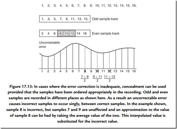
Concealment is made possible by rearranging or shuffling the sample sequence prior to recording. This is shown in Figure 17.13 where odd-numbered samples are separated from even-numbered samples prior to recording. The odd and even sets of samples may be recorded in different places, so that an uncorrectable burst error only affects one set. On replay, the samples are recombined into their natural sequence, and the error is now split up so that it results in every other sample being lost. The waveform is now described half as often, but can still be reproduced with some loss of accuracy. This is better than not being reproduced at all even if it is not perfect. Almost all digital recorders use such
an odd-even shuffle for concealment. Clearly if any errors are fully correctable, the shuffle is a waste of time; it is only needed if correction is not possible.
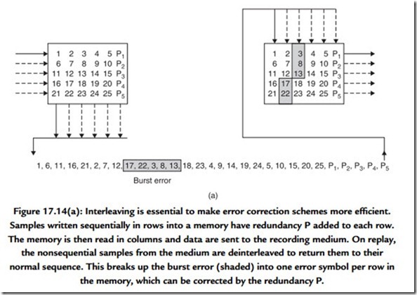
In high-density recorders, more data are lost in a given sized dropout. Adding redundancy equal to the size of a dropout to every code is inefficient. Figure 17.14(a) shows that the efficiency of the system can be raised using interleaving. Sequential samples from the ADC are assembled into codes, but these are not recorded in their natural sequence. A number of sequential codes are assembled along rows in a memory. When the memory is full, it is copied to the medium by reading down columns. On replay, the samples need to be deinterleaved to return them to their natural sequence. This is done by writing samples from tape into a memory in columns, and when it is full, the memory is read in rows. Samples read from the memory are now in their original sequence so there is no effect on the recording. However, if a burst error occurs on the medium, it will damage sequential
samples in a vertical direction in the deinterleave memory. When the memory is read, a single large error is broken down into a number of small errors whose size is exactly equal to the correcting power of the codes and the correction is performed with maximum efficiency.
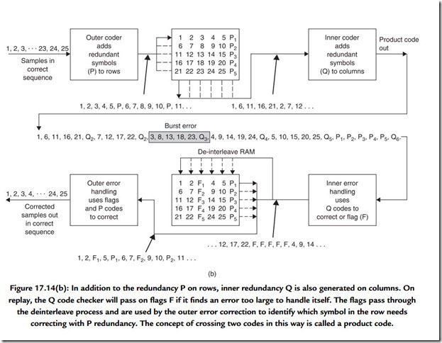
An extension of the process of interleave is where the memory array has not only rows made into code words, but also columns made into code words by the addition of vertical redundancy. This is known as a product code. Figure 17.14(b) shows that in a product code the redundancy calculated first and checked last is called the outer code, and the redundancy calculated second and checked first is called the inner code. The inner code is formed along tracks on the medium. Random errors due to noise are corrected by the inner code and do not impair the burst correcting power of the outer code. Burst errors are declared uncorrectable by the inner code, which flags the bad samples on the way into the deinterleave memory. The outer code reads the error flags in order to locate erroneous
data. As it does not have to compute the error locations, the outer code can correct more errors.
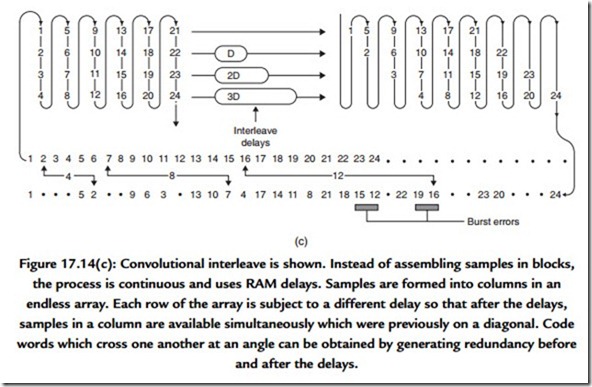
An alternative to the product block code is the convolutional cross interleave, shown in Figure 17.14(c). In this system, data are formed into an endless array and the code words are produced on columns and diagonals. The compact disc and DASH formats use such a system because it needs less memory than a product code.
The interleave, deinterleave, time-compression, and time base-correction processes cause delay and this is evident in the time taken before audio emerges after starting a digital machine. Confidence replay takes place later than the distance between record and replay heads would indicate. In DASH format recorders, confidence replay is about one-tenth of a second behind the input. Synchronous recording requires new techniques to overcome the effect of the delays.
The presence of an error-correction system means that the audio quality is independent of the tape/head quality within limits. There is no point in trying to assess the health of a
machine by listening to it, as this will not reveal whether the error rate is normal or within a whisker of failure. The only useful procedure is to monitor the frequency with which errors are being corrected and to compare it with normal figures. Professional digital audio equipment should have an error rate display.
Some people claim to be able to hear error correction and misguidedly conclude that the aforementioned theory is flawed. Not all digital audio machines are properly engineered, however, and if the DAC shares a common power supply with the error correction logic, a burst of errors will raise the current taken by the logic, which loads the power supply and can interfere with the operation of the DAC. The effect is harder to eliminate in small battery-powered machines where space for screening and decoupling components is hard to find, but it is only a matter of design: there is no flaw in the theory.
Channel Coding
In most recorders used for storing digital information, the medium carries a track that reproduces a single waveform. Clearly data words representing audio samples contain many bits and so they have to be recorded serially, a bit at a time. Some media, such as CD, only have one track, so it must be totally self-contained. Other media, such as DCC, have many parallel tracks. At high recording densities, physical tolerances cause phase shifts, or timing errors, between parallel tracks and so it is not possible to read them in parallel. Each track must still be self-contained until the replayed signal has been time base corrected.
Recording data serially is not as simple as connecting the serial output of a shift register to the head. In digital audio, a common sample value is all zeros, as this corresponds to silence. If a shift register is loaded with all zeros and shifted out serially, the output stays at a constant low level, and nothing is recorded on the track. On replay there is nothing to indicate how many zeros were present or even how fast to move the medium. Clearly serialized raw data cannot be recorded directly, it has to be modulated into a waveform that contains an embedded clock irrespective of the values of the bits in the samples.
On replay a circuit called a data separator can lock to the embedded clock and use it to separate strings of identical bits.
The process of modulating serial data to make it self-clocking is called channel coding. Channel coding also shapes the spectrum of the serialized waveform to make it more efficient. With a good channel code, more data can be stored on a given medium.
Spectrum shaping is used in CD to prevent data from interfering with the focus and tracking servos and in RDAT to allow rerecording without erase heads.
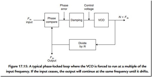
A self-clocking code contains a guaranteed minimum number of transitions per unit time, and these transitions must occur at multiples of some basic time period so that they can be used to synchronize a phase locked loop. Figure 17.15 shows a phase-locked loop that contains an oscillator whose frequency is controlled by the phase error between input transitions and
the output of a divider. If transitions on the medium are constrained to occur at multiples of a basic time period, they will have a constant phase relationship with the oscillator, which can stay in lock with them even if they are intermittent. As the damping of the loop is a low-pass filter, jitter in the incoming transitions, caused by peak-shift distortion or by speed variations in the medium, will be rejected and the oscillator will run at the average frequency of the off-tape signal. The phase-locked loop must be locked before data can be recovered, and to enable this, every data block is preceded by a constant frequency recording known as a preamble. The beginning of data is identified by a unique pattern known as a sync pattern.
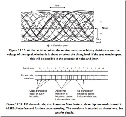
Irrespective of the channel code used, transitions always occur separated by a range of time periods which are all multiples of the basic clock period. If such a replay signal is viewed on an oscilloscope, a characteristic display called an eye pattern is obtained. Figure 17.16 shows an eye pattern, and in particular the regular openings in the trace. A decision point is in the center of each opening, and the phase-locked loop acts to keep it centered
laterally, in order to reject the maximum amount of jitter. At each decision point along the time axis, the waveform is above or below the point, and can be returned to a binary signal.
Occasionally, noise or jitter will cause the waveform to pass the wrong side of a decision point, and this will result in an error that will require correction.
Figure 17.17 shows an extremely simple channel code known as frequency modulation (FM), which is used for the AES/EBU digital interface and for recording time code on tape.
Every bit period begins with a transition, irrespective of the value of the bit. If the bit is a one, an additional transition is placed in the center of the bit period. If the bit is a zero, this transition is absent. As a result, the waveform is always self-clocking irrespective of the values of the data bits. Additionally, the waveform spends as much time in the low state as it does in the high state. This means that the signal has no DC component and will pass through capacitors, magnetic heads, and transformers equally well. However simple FM may be, it is not very efficient because it requires two transitions for every bit and jitter of more than half a bit cannot be rejected.
More recent products use a family of channel codes known as group codes. In group codes, groups of bits, commonly eight, are associated together into a symbol for recording purposes. Eight-bit symbols are common in digital audio because two of them can represent a 16-bit sample. Eight-bit data have 256 possible combinations, but if the waveforms obtained by serializing them are examined, it will be seen that many combinations are unrecordable. For example, all ones or all zeros cannot be recorded
because they contain no transitions to lock the clock and they have excessive DC content. If a larger number of bits is considered, a greater number of combinations is available. After the unrecordable combinations have been rejected, there will still be 256 left which can each represent a different combination of eight bits. The larger number of bits are channel bits; they are not data because all combinations are not recordable. Channel bits are simply a convenient way of generating recordable waveforms. Combinations of channel bits are selected or rejected according to limits on the maximum and minimum periods between transitions. These periods are called run-length limits and as a result group codes are often called run-length-limited codes.
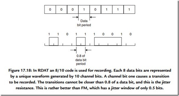
In RDAT, an 8/10 code is used where 8 data bits are represented by 10 channel bits. Figure 17.18 shows that this results in jitter rejection of 80% of a data bit period: rather better than FM. Jitter rejection is important in RDAT because short wavelengths are used and peak shift will occur. The maximum wavelength is also restricted in RDAT so that low frequencies do not occur.
In CD, an 8/14 code is used where 8 data bits are represented by 14 channel bits. This only has a jitter rejection of 8/14 of a data bit, but this is not an issue because the rigid CD has low jitter. However, in 14 bits there are 16K combinations, and this is enough to impose a minimum run length limit of 3 channel bits. In other words, transitions on the disc cannot occur closer than 3 channel bits apart. This corresponds to 24/14 data bits.
Thus the frequency generated is less than the bit rate and a result is that more data can be recorded on the disc than would be possible with a simple code.
