Applications of Inductive circuits
Inductive circuits are widely used in electronics.
Inductors compete with capacitors for filtering and phase-shift applications. Because inductors are larger, heavier, and more expensive than capacitors, they have fewer applications than capacitors. However, inductors have the advantage of providing a reactive effect while still completing a DC circuit path. Capacitors can pro- vide a reactive effect but block the DC elements.
Inductors are sometimes combined with capacitors to improve the performance of a circuit. The reactive effect of the capacitor then opposes the reactive effect of the inductor. The end result is that they comple- ment each other in a circuit.
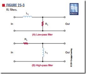
Series rL networks are used as low- and high- pass filters. Figure 25-3 shows the two basic types of filters. The circuits are essentially resistor-inductor voltage dividers. Figure 25-3A is a low-pass filter. The input is applied across the inductor and resistor. The output is taken from across the resistor. At low
frequencies, the reactance of the coil is low. There- fore, it opposes little current, and most of the voltage is dropped across the resistor. As the input frequency increases, the inductive reactance increases and offers more opposition to current flow so that more voltage drops across the inductor. With more voltage dropped across the inductor, less voltage is dropped across the resistor. Increasing the input frequency decreases the output voltage. Low frequencies are passed with little reduction in amplitude, whereas high frequencies are greatly reduced in amplitude.
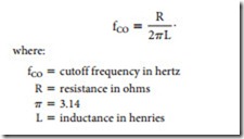
Figure 25-3B is a high-pass filter. The input is applied across the inductor and resistor, and the output is taken across the inductor. At high frequencies, the inductive reactance of the coil is high, causing most of the voltage to be dropped across the coil. As the frequency decreases, the inductive reactance decreases, offering less opposition to the current flow. This causes less voltage to be dropped across the coil and more voltage to be dropped across the resis- tor. The frequency above or below the frequencies passed or attenuated is called the cutoff frequency. The symbol for the cutoff frequency is fco. The cutoff
frequency can be determined by the formula:
Questions
1. What are the disadvantages of using inductors in circuits?
2. What are the advantages of using inductors in circuits?
3. Draw a diagram of an RL low-pass filter, and explain how it operates.
4. Draw a diagram of an RL high-pass filter, and explain how it operates.
5. How can the cutoff frequency of an RL circuit be determined?
Summary
● In a pure inductive circuit, the current lags the applied voltage by 90°.
● Inductive reactance is the opposition to current flow offered by an inductor in an AC circuit.
● XL represents inductive reactance.
● Inductive reactance is measured in ohms.
● Impedance is the vector sum of the inductive reactance and the resistance in the circuit.
Series RL circuits are used for low- and high-pass filters.
Related posts:
Incoming search terms:
- Advantages & disadvantages of Ac inductive circuit
- advantage of using inductor in AC circuit
- inductive circuits
- applications of inductive ac circuits
- applications for inductive ac circuits
- application of purely inductive circuit
- application of purely inductive AC circuits
- application of inductive circuit
- aplliacation of a resistive a c circuit
- Advantages & disadvantages of using Ac inductive circuit
- pure inductive ac cicuit

