Slot and Bar Marking
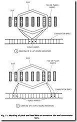
Slot and bar marking is an important operation, since incorrect lead throw causes sparking and poor operation. Markings on the core indicate the slots in which the top half and bottom half of a coil are inserted. It also prevents winding a right-hand coil when a left hand winding is indicated, or vice versa. When scribed on the armature, these marks make a permanent record of the coil and commutator pitch for both lap or wave winding, progressive or retrogressive. Marking is done as follows, Fig. 11.
1. Mark the tooth on each side of the slot which contains the top half of a coil chosen for recording preliminary data, with two crosses or two center-punch marks,(x/x ) or(:). Make the two crosses with a three-cornered file.
2. For a lap winding, center-punch one mark on the end of the commutator bar to which the lead from the slot previously marked is connected. For a wave winding, center-punch two marks (:).
3. Mark the teeth on each side of the slot which contains the bottom half of the same coil chosen for recording preliminary data, with one cross or one center-punch mark, (x) or (.). Make the cross with a three-cornered file.
4. Center-punch one mark on the commutator bar, to which the lead from the slot previously marked is connected, with one cross or one center-punch mark. Do this for either a lap winding or a wave winding.
Removal of the Commutator
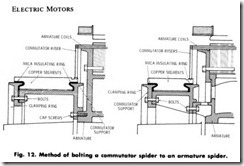
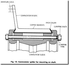
If the winding is deteriorated and brittle, it is advantageous to remove the commutator to acquire data while stripping. On large armatures the commutator is built upon a strong flange-like support or shell .. bolted to the armature spider, Fig. 12, or mounted on a separate spider secured to the shaft, Fig. 13. On small machines, the commutator hub is usually of cast iron (Fig. 14) keyed and pressed onto the shaft. The following procedure will aid in removing a commutator and identifying the leads of a coil:
1 . Remove all bands.
2 . Locate a top coil, that is, a coil which is exposed across the rear end of the armature from slot to slot.
3. Remove the wedges from the slots which house this coil.
4. Cut or disconnect the coil lead or leads from the commutator bar to which it is connected for one coil side. It may be necessary to remove more than one lead from the commutator bar to locate the top coil lead.
5. Cut or disconnect the coil lead or leads from the commutator bar to which the other side of the located coil is connected.
6. Count and record the number of bars on the commutator spanned by the coil leads. This is the commutator pitch.
7. Check and cross-check the disconnected coils with an ohmmeter for a resistance check between the coil leads. The coil which registers the lowest resistance is the single coil.
8. Identify the single coil leads with tape or colored sleeving.
9. Count and record the number of slots spanned by the single coil.
This is the coil pitch.
10. Record the wire size and type of wire insulation.
11 . Remove all remaining leads from the commutator.
12. Remove all space fillers and tapes from behind the commutator risers until the shaft is exposed.
13. Record the distance of the shaft from the core to the commutator.
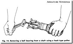
14 . Remove the commutator with a hook type puller and arbor plates.
Fig. 14. The procedures below will aid in placing and using the hook type puller for this application.
a. Place a pair of proper-fitting arbor plates behind the commu tator.
b. Adjust the hooks for the hook type puller to the arbor plates and adjust the jackscrew to the armature shaft.
a. Slowly tighten the jackscrew until the commutator starts to move from the shaft.
b. Continue tightening the jackscrew until the commutator is finally removed from the shaft.
c. Place the commutator in a safe place for a later check.
Wedge Removal
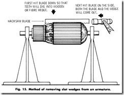
The wedges can be removed by using a piece of power-hacksaw blade with the sharp edges on the broken ends and the set of the teeth ground off. They can also be removed with a commercially manufac tured, wedge-removing tool.
1. Place the hacksaw blade or armature- wedge remover on top of the wedge in the slot so that the teeth will bite into the wedge.
2. Tap the hacksaw blade with a hammer, in the direction which the teeth point, Fig. 15. This should be so that the teeth are embedded in the wedge.
3. Continue tapping the hacksaw blade with the hammer until the wedge is driven out.
After the Commutator Is Removed
The remaining parts of the armature may now be subjected to either of two methods for loosening the impregnated varnish. One method is the application of heat with an acetylene torch flame, the other is the immersion of the entire unit in a caustic soda solution.
1. Application of heat. Use a large stem on the handle assembly of an acetylene brazing and soldering set for applying heat to the armature core. Follow the procedure set forth below.
a. Remove all slot wedges.
b. Place the armature (without the commutator) in a metal stand which is clear of all flammable materials.
c. Light the torch and apply the flame to all parts of the armature core by slowly moving the torch flame. Concentrate applica tion on the core slots and the windings. Do not permit the flame to stay too long on the shaft. If the shaft gets too hot, its temper may be affected.
d. Continue applying the torch flame to the windings until the insulation has become charred and shrunken sufficiently for the coi I conductors to become loosened.
e. Allow the armature to cool.
2. Application of caustic soda. Use of caustic soda solution for loosening the windings:
a. Remove all the wedges.
b. Place the armature (without the commutator) in large pan or vat which is deep enough to hold sufficient caustic soda solution to cover the armature.
c. Place the pan or vat on an electric hot plate or gas burner.
d. Slowly pour in the caustic soda solution.
WARNING: Wear rubber gloves and carefully handle caustic soda solution. Prevent it from splashing. Caustic soda solution can cause serious burns or injuries.
e. Heat the solution until it attains boiling temperature.
f. Remove from the heat and allow the armature to soak until the varnish softens.
g. Remove the armature from the pan or vat. Soak and flush the
armature with clean water until the caustic soda solution has been weakened to the point where it is noninjurious.
h. Allow the armature to drain.
Testing the Commutator for Grounds and Short Circuits Between Bars
While waiting for the armature to cool or drain, it will be advan tageous to check the commutator which has been previously removed. Follow the procedure set forth below:
1. Clean out the commutator connection slots.
2. Blow out metal chips and dirt with compressed air.
3. Check for solder which may have lodged between bars and remove any which is found.
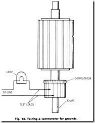
4. Use a test light or ohmmeter to check for grounds. Fig. 16.
4. Connect one lead of the tester to the commutator sleeve and touch the other lead to a commutator bar. If the lamp lights or the ohmmeter registers, the bar is grounded and the cause must be
removed. Continue this check for every bar. Fig. 16.
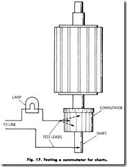
5. Touch the one lead of a test light or ohmmeter to a bar and the other lead to an adjacent bar. If the lamp lights or the ohmmeter registers, one bar is short-circuited to the other. Remove the cause. Continue this check for every bar, Fig. 17.
6. After checking and servicing, store the commutator in a safe place until it is needed for reassembly.
STRIPPING PROCEDURE
After all bands and wedges have been removed and the top coil has been located, checked, recorded, and identified, proceed as follows:
1 . Cut or disconnect the lead or leads of the next exposed coil from the commutator bar to which it is connected for one coil side.
2 . Remove the wedges from the slots which house this coil.
3 . Check for the lead from the top coil by lifting the disconnect leads, one at a time, until one is found which can be lifted comparatively easily along the entire length of the slot.
4 . Count and record the number of turns removed by continually unwinding the coil until it is entirely removed.
5 . Check the turns count against the turns count of the previously removed coil. The count should not vary more than two turns.
6 . Check and record the type of winding, wave or lap, progressive or retrogressive.
7 . Remove all slot wedges.
8 . Cut or disconnect all remaining commutator connections.
9 . Record the wire size and type of wire insulation.
1 0 . Remove all space fillers and tapes from behind the commutator risers until the shaft is exposed.
1 1 . Cut the coils at both ends.
1 2 . Remove the coil conductors from the slots.
1 3 . Remove all the old insulations.
1 4 . Clean the slots with a file.
1 5 . File all burrs smooth.
1 6 . Clean the back of the commutator.
1 7 . Clean excess solder and broken particles of copper out of the bar slots using a hacksaw blade that will make a cut in the bar no larger than the diameter of the new wire.
1 8 . Test check the commutator.
Stripping Procedure with the Commutator Removed
If, after treating the armature windings as outlined in the stripping procedure with the commutator intact, it is found that the windings are still hard to remove, follow the following procedure:
1 . With a hacksaw, cut the ends of the windings flush with the core, or place the armature in a lathe and use a V-shaped pointed tool to remove the end windings at each end of the core.
2 . Remove the armature from the lathe or stand.
3 . Pile up two rows of wooden blocks to a height which will accommodate the full length of the armature shaft. Have the core rest vertically upon the wooden blocks and the end of the shaft
just clear of the workbench.
4 . Drill a hole, larger than the width of the slot, into one set of the wooden blocks.
5 . Align a slot with the hole in the wooden block. The purpose of aligning a slot with the drilled hole in the wooden blocks is to prevent the outside laminations of the core from becoming dis torted or warped when the coil conductors are driven out.
6 . Use a hammer and drift punch to knock out the coil conductors from the slots.
7 . Follow steps 5 and 6 above for all the slots.
8 . Check the drilled hole occasionally and clear it of the coil-con ductor accumulations to provide clearance for successive coil conductors which are driven into it.
9 . Remove all the old insulations.
10 . Clean the slots with a file.
11. File all burrs smooth
SUMMARY
Armature windings are classified into two main groups: lap windings and wave windings. Either group can be arranged progressively or retrogressively and connected in simplex, duplex or triplex.
Commutator pitch is the term used to refer to the number of bars between coil leads. Coil pitch is the number of slots between coil sides. Lead swing is the direction a lead takes from a coil side to its connection on a commutator bar.
One of the most important tasks of any rewinding operation is the accurate recording of data concerning the armature being rewound. Slot and bar marking is an important operation, since incorrect lead throw causes sparking and poor operation. If the winding is deteriorated and brittle, it is advantageous to remove the commutator to acquire data while stripping.
The wedges can be removed by using a piece of hacksaw blade with the sharp edges on the broken ends and the set of the teeth ground off. After the commutator is removed the remaining parts of the armature may be subjected to either of two methods for loosening the impreg nated varnish. While waiting for the armature to cool or drain, it is advantageous to check the commutator which has been previously removed. The check for grounds and shorts can now be performed. The commutator can be removed before stripping the armature or it can be stripped before it is removed.
REVIEW QUESTIONS
1. What are the two main types of armature windings?
2. What is a simplex winding?
3. What is a simplex progressive lap winding?
4. What is commutator pitch?
5. What is coil pitch?
6. What is lead swing?
7. Why is data recording important before a rewinding operation?
8. What data should you take while stripping the armature?
9. Why should bars and slots be marked?
10. Why should a commutator be removed?
11. How are wedges removed?
12. How do you test a commutator for grounds and short circuits between bars?
13. How do you strip an armature with the commutator intact?
14. How do you strip an armature with the commutator removed?
