Fibre-optic applications
The increasing use of optical fibres along with photosensors and optical transducers has led to the development of a range of devices that are specially intended for use with fibres. The detecting devices are photo- diodes, so that the principles are the same as have already been discussed, but the physical form of each device must be suited to coupling to the fibre-optic cable. Fibreptic links have become a practical proposition only since suitable terminations and connectors were developed, and it is futile to expect to be able to couple a general-purpose type of photodiode or emitter to a fibre cable. Several manufacturers offer complete fibre systems, composed of emitters, detectors, couplers and cables for either experimental work, assessment, or production use.
Light transducers
The conversion of energy between electrical and light forms has been of con- siderable importance for more than a century. The conversion of electrical energy into light has been, and still is, performed mainly by using the elec- trical energy to heat a coil of wire to a high temperature so that it gives out light. The light spectrum that is obtained in this way depends on the temperature of the object, and practical limitations usually result in the light having a spectrum that is biased to the red, so that the light from sources of this type, i.e., incandescent sources, is unsuitable for colour matching. This type of transducer is, however, the simplest to manufacture and use. It also has the lowest efficiency of conversion.
Early designs of light bulb used carbon filaments, which were fragile
(some, astonishingly, have survived and are still working), and the bulbs were evacuated to avoid oxidation of the carbon. The improvements made by Swan to the original Edison design included the use of the metal tungsten as a filament material, and the use of argon gas in the bulb. The inert nature of the gas avoided oxidation, and the pressure of the gas (although less than atmospheric pressure) avoided problems due to eva- poration of the metal of the filament. Early tungsten-filament lamps failed in an hour or less because of the blackening of the glass caused by the tungsten vapour condensing. Although blackening is still the main cause of failure, the time has been greatly extended through the use of the inert gas in the bulb.
The development of gas-discharge lamps has resulted in a variety of light sources of a very different type, all very much more efficient than the incandescent lamp (usually at least five times the conversion percentage of the filament lamp). The original types of gas-discharge devices used gases such as neon at low pressure, so that high voltages in the range 1-15 kV were needed to operate the devices. These were, and are, the familiar neon signs, in which the gas is nowadays seldom neon but more usually a mixture of gases that have been chosen to achieve some particular colour. The colour of the light from discharge tubes is the colour of the predominant spectral lines of the gas or vapour that is used, and this leads to the light being in many cases almost monochromatic, or of one single colour. Low- pressure discharge lamps are, therefore, unsuitable for general application to illumination and they remain used predominantly for advertising signs.
Vapours of liquids and solids have also been used in discharge lamps, and the most familiar of these are the mercury and sodium lamps that are used for street illumination. Used at low pressures, these vapours give strongly coloured light in which colour discrimination is almost impossible, but when higher pressures are used, the light spectrum broadens to give results that are more acceptable. The sodium high-pressure lamps are considerably more visible in fog, due to the orange-red predominance in the light, and are used extensively for motorway and main road illumination.
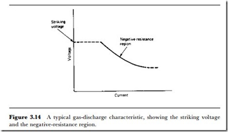
All varieties of discharge lamps require control gear, in the sense that they cannot simply be connected to a voltage source. Figure 3.14 illustrates the normal current-voltage characteristic of a discharge lamp, and shows that no current passes until a critical voltage is reached across the terminals. From that point (the ignition voltage), the voltage across the gas drops as the current is increased, a negative-resistance characteristic. This would cause the lamp to burn out if there was no way of controlling the current.
These lamps are therefore normally operated with AC, using an inductor (choke) in series with the supply if the running voltage is less than the supply voltage, or a transformer with current-limiting inductance if the running voltage is higher than normal supply voltage. This additional equipment reduces the overall efficiency of the lamp, but is an essential part of the system.
For domestic use, the familiar fluorescent tube has been available for some considerable time now. This is not such a physically simple device as the older types of discharge tube, however, because it incorporates two energy conversions in series. The conversion from electrical to light energy is made by a discharge through mercury vapour at a pressure less than atmospheric, but this results in light that is mostly in the violet and ultravio- let range. The tube is coated on the inside with a phosphor material that acts as a frequency-changer. The violetjultraviolet light from the mercury discharge causes energy changes in the atoms of the phosphor material, and as these changes are reversed, the energy is given out again as light in the normal range of visible light.
This system is very flexible, because the colour and composition of the light that is given out depends on the phosphor coating rather than on the mercury discharge. The phosphors are metal silicates with controlled amounts of impurity, and very small changes in composition can cause marked differences in both conversion efficiency and spectrum – the materials are essentially the same as those used for cathode ray tube coatings. Because of this, fluorescent tubes can be bought in almost any colour, and most importantly in a ‘sunlight’ version whose spectral make- up is that of mid-day sunlight, ideal for colour matching. For domestic purposes, tubes labelled as ‘warm’ give a light that is more biased to red than the daylight type so that the light output is rather closer to that of the
incandescent lamp. Even with the double conversion, the fluorescent is almost five times as efficient as an incandescent lamp.
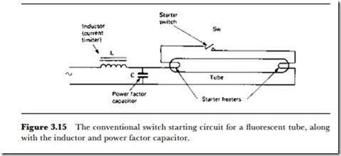
The control gear of the fluorescent will be either of the switch-start or the quick-start variety. The switch-start type uses the conventional inductor (choke) in series with the tube, and a capacitor for power-factor correction. The starting voltage of the tube is higher than the supply voltage, and the mercury must be vaporized in order to achieve sufficient vapour pressure for starting. This makes starting difficult in cold conditions, which is why a fluorescent in a garage or a loft often fails to light in the winter. The starting circuit (Figure 3.15) contains a thermal timeswitch that will pass current through the heating filaments when the tube is first turned on, and then break this circuit. At the instant when the switch breaks contacts, the back-EMF generated in the inductor causes the voltage across the tube momentarily to exceed the ignition voltage, so that the discharge starts and will then continue if the mercury vapour pressure is high enough. The current is then limited by the choke.
The alternative arrangement uses a transformer with separate windings for the heater filaments, and a high-impedance output greater than the ignition voltage for the main discharge. At switch-on, the filaments are heated and the ignition voltage is applied, so that the tube lights without the flickering or long delay that can be an annoying feature of switch starters. The high impedance of the secondary transformer then controls the tube current.
A more modern variation on this scheme uses an electronic converter to generate the heater and main voltages, so that the tube can be made with its control gear in one unit, and plugged directly into a domestic lamp socket. Tubes of this type are now readily available for domestic use, and combine long life with high efficiency. Other tubes with incorporated control gear still use the switch-start principle and so exhibit the disadvantages of slow flickering starts. All domestic fluorescent lamps of the compact type have a slow warm-up, so that the normal light output is not attained until the lamps have been in action for several minutes.

