Inductors, like capacitors, oppose current flow in AC circuits. They may also introduce a phase shift between the voltage and the current in AC circuits.
A large number of electronic circuits are composed of inductors and resistors.
Inductors In Ac circuits
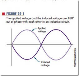
Inductors in AC circuits offer opposition to current flow. When an AC voltage is placed across an inductor, it creates a magnetic field. As the AC voltage changes polarity, it causes the magnetic field to expand and col- lapse. It also induces a voltage in the inductor coil. This induced voltage is called a counter electromotive force (cemf); the greater the inductance, the greater the cemf. The cemf is out of phase with the applied voltage by 180° (Figure 25-1) and opposes the applied voltage. This opposition is as effective in reducing cur- rent flow as a resistor.
The amount of voltage induced in the inductor de- pends on the rate of change of the magnetic field. The faster the magnetic field expands and collapses, the greater the induced voltage. The total effective volt- age across the inductor is the difference between the applied voltage and the induced voltage. The induced voltage is always less than the applied voltage.
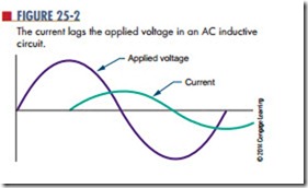
Figure 25-2 shows the relationship of the current to the applied voltage. In a purely inductive circuit, the current lags behind the applied voltage by 90°. Another way of stating this is that the applied voltage leads the current by 90° in a pure inductive current.
This can be represented by the acronym ELI. Voltage the current lags the applied voltage in an AC inductive circuit.
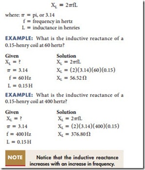
The opposition offered to current flow by an induc- tor in an AC circuit is called inductive reactance and is measured in ohms. The amount of inductive reactance offered by an inductor depends on its inductance and the frequency of the applied voltage. The larger the inductance, the larger the magnetic field generated and the greater the opposition to current flow. Also, the higher the frequency, the greater the opposition the inductor has to current flow.
Inductive reactance is expressed by the symbol XL and is determined by the following formula:
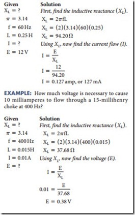
Ohm’s law applies to inductive reactance in AC circuits in the same manner that it applies to resistance. The inductive reactance in an AC circuit is directly proportional to the applied voltage and inversely proportional to the current. This relationship is expressed as
The current increases with an increase in voltage or a decrease in the inductive reactance. Likewise, decreasing the voltage or increasing the inductive reactance causes a decrease in current.
EXAMPLE: How much current flows through a 250-millihenry inductor when a signal of 12 volts and 60 hertz is applied across it?
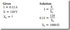
EXAMPLE: What is the inductive reactance of a coil that has 120 volts applied across it with 120 milliamperes of current flow?
The impedance of a circuit containing both induc- tance and resistance is the total opposition to current flow by both the inductor and the resistor. Because of the phase shift caused by the inductor, the inductive reactance and the resistance cannot be added directly. The impedance (Z) is the vector sum of the induc- tive reactance and the resistance in the circuit. The impedance is expressed in ohms and is designated by the letter Z. Impedance can be defined in terms of Ohm’s law as:
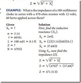
The most common inductive circuit consists of a resistor and an inductor connected in series. This is referred to as an RL circuit. The impedance of a series RL circuit is the square root of the sum of the squares of the inductive reactance and the resistance. This can be expressed as:
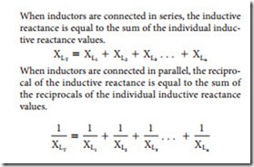
When inductors are connected in series, the inductive reactance is equal to the sum of the individual induc- tive reactance values.
Questions
1. What does an AC voltage do when applied across an inductor?
2. What is the relationship between current and voltage in an inductive circuit?
3. What is inductive reactance?
4. What is the inductive reactance of a 200-millihenry inductor at 10,000 hertz?
5. How is the impedance determined for an inductor-resistor network?
