DEVELOPING A WIRING DIAGRAM (CIRCUIT #3)
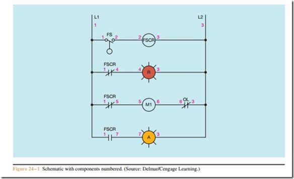
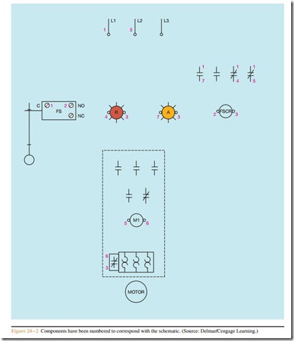
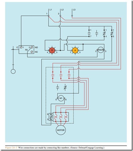
Figure 24 – 1 shows the same schematic as Figure 21 – 1, except that Figure 24 – 1 has been labeled with numbers. Figure 24 – 2 shows the components of the wiring dia- gram labeled with numbers that correspond to the num- bered components shown in the schematic. Figure 24 – 3 shows the wiring diagram with connected wires.
The same method has been used to number the circuits in the last few chapters. Although most control schematics are numbered to aid the electrician in troubleshooting, several methods are used. Regardless of the method used, all numbering systems use the same principles. An electrician who learns this method of numbering a schematic will have little difficulty understanding a different method.
Review Question
1. Are numbering systems other than the one described in this text used to develop wiring diagrams from schematic diagrams?


