DIGITAL MODULATION AND WIRELESS TRANSMISSION METHODS
In Chapter 7, basic digital modulation methods ASK/OOK and FSK were covered. These are not used except for an advanced FSK as used in GSM. Instead, all cellular systems used advanced digital modulation methods. This section provides a look at these techniques.
Quadrature Amplitude Modulation
Quadrature amplitude modulation (QAM) is a technique that mixes both amplitude and phase variations in a carrier at the same time. What this technique does is to allow higher data rates within the same bandwidth. See the sidebar on spectral efficiency. The technique consists of transmitting multiple bits for each time interval of the carrier symbol. The term “symbol” means some unique combination of phase and amplitude. The term M as in M-QAM indicates how many bits are transmitted per time interval or symbol for each unique amplitude/phase combination.
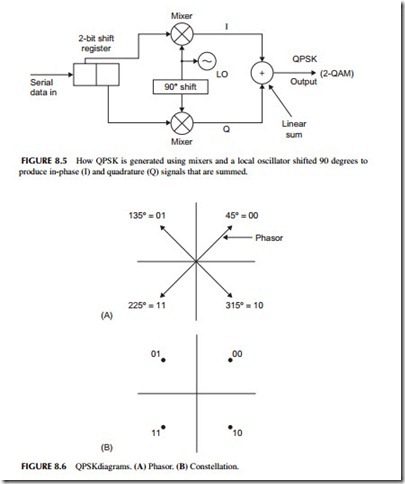
The simplest form of QAM is 2-QAM, more commonly called QPSK or quadrature phase shift keying. It is produced by the circuit shown in Figure 8.5. It takes the serial bitstream and passes it through a 2-bit shift register producing two parallel bitstreams at half the rate. One is called the in-phase (I) bit- stream and the other the quadrature (Q) bitstream. The I and Q signals are each applied to a mixer along with a local oscillator (LO) signal. The mixer output becomes part of the RF carrier. Note that the LO signal is applied directly to one mixer, but is shifted by 90 degrees and applied to the other mixer. The term
signals but at different phases. But when they are added together, the QPSK signal is generated. With this arrangement, you can transmit data at twice the rate of BPSK in the same bandwidth.
Figure 8.6 shows how we illustrate this with what we call the phasor and constellation diagrams. Figure 8.6A shows the amplitude and phase of each possible combination of 2 bits. The length of the arrow called a phasor is the amplitude, and its direction or angle is the phase. If the receiver gets a signal that is at a phase angle of 135 degrees, it means that the 2-bit combination 01 is being transmitted. The constellation diagram in Figure 8.6B is usually shown without the arrows or phasors.
This technique can be modified to produce 16-QAM, which transmits 4 bits per time interval or symbol causing the data rate to quadruple in the same bandwidth. The circuit for producing 16-QAM is shown in Figure 8.7. The 4-bit shift register produces two groups of I and Q bits. These are converted into four levels by a two- to four-level converter that works like a digital-to-analog converter (DAC). The resulting constellation diagram for 16-QAM is shown in Figure 8.6 as well. Other common versions are 64-QAM and 256-QAM, which transmit 6 and 8 bits per symbol, respectively, in the same bandwidth.
QPSK and QAM modulation methods are common in cable TV for digital TV as well as high-speed Internet service. They are also used with satellites and any broadband wireless application. All modern cell phones and most other digital wireless schemes use this type of modulation because of its spectral efficiency.
Orthogonal Frequency Division Multiplexing
Orthogonal frequency division multiplexing (OFDM) is a broadband modulation method like spread spectrum/CDMA. It takes a high-speed serial binary
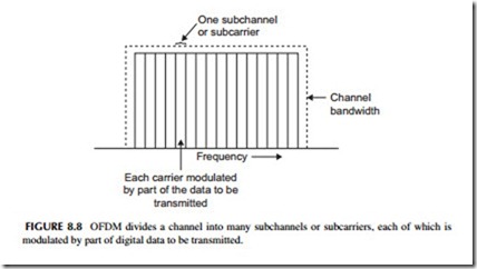
signal and spreads it over a wide bandwidth. The serial data is passed through a circuit that maps out the constellation diagram for the modulation to be used. It then divides it into many slower-speed serial bitstreams. Each bitstream modulates a carrier on one of many adjacent carriers in the available bandwidth. This technique effectively divides a wide bandwidth into many narrower subchannels or subcarriers as shown in Figure 8.8. Sometimes dozens of channels are used, and in other cases hundreds or even thousands of carriers are used. The carrier frequencies are selected so they are orthogonal and as a result they will not interfere with one another even though they are directly adjacent. All the modulated channels are then added together and the combination transmitted in the available bandwidth. The type of modulation varies with the application but it is usually BPSK, QPSK, 16-QAM, or 64-QAM.
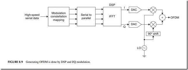
The basic technique is shown in Figure 8.9. The only practical way to cre- ate an OFDM signal is by using DSP. The DSP executes an algorithm called the inverse fast Fourier transform (IFFT) that creates the multiple adjacent modulated carriers. The DSP data is applied to DACs to create I and Q signals that are sent to mixers for creation of the final signal. At the receiver, the data is recovered by another DSP executing the FFT. The output is the original fast serial data.
OFDM seems impossibly complex while seemingly hogging spectrum space. Yet, it can transmit higher speeds in smaller bandwidths than most other types of digital modulation. It is very spectrally efficient. Furthermore, it is more resistant to multipath interference that can cause microwave links to lose data due to a reflected signal interfering with another or a direct signal causing cancellation and fading. Most of the new wireless technologies today use OFDM, including the forthcoming LTE cellular systems. Some examples of other OFDM uses include wireless local area networks (WLAN), wireless broadband (WiMAX), digital subscriber line (DSL) Internet access, digital TV, and AC power-line networking.
Multiple Input Multiple Output
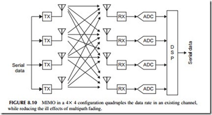
Another technique for boosting speed within a given bandwidth is multiple input multiple output (MIMO). Also known as spatial multiplexing, it is the use of multiple transmitters transmitting to multiple receivers, each sending different bitstreams on the same channel. The high-speed serial data is divided into two, three, four, or even more bitstreams, and each is used to modulate a different transmitter but operating on the same frequency. The signals from each transmitter reach the antennas of each receiver along with any reflected signals. See Figure 8.10, which shows four transmitters (Tx) and four receivers (Rx) or 4 X 4 MIMO. What allows the receivers to sort out each bitstream is the fact that each signal travels a different path, and will have different characteristics or spatial signature that can be sorted out by DSP in the receiver.
There are several things that make MIMO practical. First, MIMO is used at very high frequencies, especially microwave (>1 GHz). This means that antennas are short and inter-antenna space may be one wavelength or more, which is required for MIMO to work. The distance between the antennas ensures different spatial paths with different characteristics that let the receivers recover each bitstream. Second, thanks to semiconductor technology, it is possible to make the multiple transmitters and receivers very inexpensively, typically all on a single silicon chip.
MIMOhas several benefits. First, it allows a higher data rate in the same channel bandwidth. Using a 4 X 4 MIMO, for example, would boost speed by a factor of 4. Configurations of MIMO can be any combination of trans- mitters and receivers. The 2 X 2 mode is popular but 4 X 4 is also used. Second, MIMO provides a more reliable link. It actually takes advantage of the multipath problems that usually plague microwave wireless and makes it
better. Finally, MIMO is usually combined with OFDM, which provides the ultimate data-rate boost, reliability, and spatial efficiency. MIMO is already used in wireless local area networks (WLAN) like Wi-Fi and in broadband wireless systems using WiMAX. Both of these technologies will be covered in the next chapter. MIMO will also be used with LTE, the next cell phone system. No, handsets probably will not have multiple antennas but the base stations will.
Spectral Efficiency
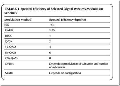
Spectral efficiency refers to how much data you can transmit in a given band- width. It is usually measured in bits per second per hertz (bps/Hz). ASK/OOK and FSK have efficiencies of <1. Special forms of FSK, such as Gaussian minimum shift keying (GMSK) used with GSM cell phones, are a bit better. BPSK has a spectral efficiency of 1. Table 8.1 gives the efficiencies of most of the popular digital wireless modulation schemes.
One last thing: the type of modulation is not the only thing that affects spectral efficiency. The level of noise in a channel also determines the number of bit errors that occur in transmission. The higher levels of QAM have more errors, so this limits their efficiency to some extent. Plain FSK, BPSK, and QPSK are very resistant to noise, so are more suitable in applications where noise is a problem. Noise and bit rates have to be traded off for good reliable transmission. And by the way, the spectral efficiency issue applies to wired as well as wireless communications channels.
Related posts:
Incoming search terms:
- what are the modulation schema used in mobile phone
- half duplexing uses whatmodulation
- modulation in mobile phones
- ask psk fsk advanced fsk OFDM modulation in wireless communications
- what is the type of modulation appilied in cellphones
- what type of modulation is used in cell phones
- what types of modulation are used with cellular phone?
- what use of modulation of cell phones
- which modulation is used in cellular phones
- which modution technic use in mobile
- type of modulation used in mobile phones
- type of modulation used in mobile phone
- modulation techniques used in cell phones
- modulation technique used in mobile phones
- modulation schemes used in mobiles
- modulation in cell phone
- compare GMSK and QAM
- cellphone modulation schemes
- cell phone signal modulation
- wireless modulation technique used in mobile phones
