Electrophotographic printer service techniques
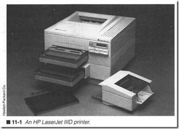
ELECTROPHOTOGRAPHIC (EP) PRINTERS USE A COMPLEXcombination of light, static electricity, heat, chemistry, and pres sure, all guided by a fairly complex ECU (figure 11-1). EP printing is not a “one-step” action as it is with impact, thermal, or ink jet systems. There is no one single part responsible for applying plint; EP printers use a series of individual assemblies that make up its Image Formation System (IFS). Because EP image formation uses a “process” rather than a “print head,” there are many more vari able conditions that will affect the print’s ultimate quality and ap pearance. Now that you have seen how EP printers work and learned the operation of basic power supplies, electronic controls, and mechanical systems, this chapter will present detailed expla nations and troubleshooting procedures specifically for EP print ers.
Inside the EP printer
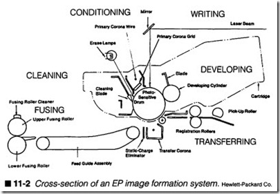
Before proceeding with specific symptoms, you should have a thorough understanding of the EP printer’s internal components. Figure 11-2 illustrates a complete cross-section of an image for mation system. Each of the major components and subassemblies are clearly pointed out. Paper starts in the paper tray. When a printing cycle begins, a feed roller (also called a paper pick-up roller) grabs the next sheet in the tray. A separation pad below the feed roller helps to ensure that only one page at a time actually enters the printer. The feed roller positions the page against a set of registration rollers that hold the sheet in place until the drum image is synchronized with the paper’s top margin. A transfer roller carries the page past the transfer corona where high voltage places a large charge on the page. As the page continues to move near the EP drum, the latent image developed in the drum will be transferred to the page. A feed guide carries the developed page to the fusing assembly where the upper fusing roller applies heat, and the lower fusing roller applies pressure, fiXing the image to the page. The page moves up the printer where it is grabbed by the delivery assembly and ejected to the face-down tray.
There are additional assemblies that you should be familiar with in the SX-type engine. A set of erase lamps (3) cleans any charges off the drum, while a primary corona (4) applies an even conditioning charge to the drum surface. Once the drum is cleaned and condi tioned, it is ready to receive an image from the writing mechanism.
Writing is accomplished with a laser/scanning assembly (6). The laser beam is modulated by the printer’s logic and swept by a ro tating polygon mirror. The swept beam leaves the assembly and is reflected from a beam-to-drum mirror (5) to the drum surface. It is this latent image that is developed with toner and transferred to the page at the transfer station (13).
As you might imagine, trouble in any part of the printer can se riously impair the printer’s operation. For the purposes of this chapter, trouble can be broken down into eight major areas: controller problems, registration problems, fusing problems, laser/scanner problems, drive and transmission problems, high voltage power supply (HVPS) problems, transfer problems, and a small assortment of miscellaneous symptoms. This chapter shows you the symptoms and solutions for over 60 EP printer problems.
Controller (logic) systems
Most EP printers use an ECU consisting of two parts: a main board and a mechanical controller. The main board provides the core logic for the printer: CPU, memory, an interface for the control
panel, the communication circuits, and other processing elements.
The mechanical controller provides an interface between the pure logic and the electromechanical components of the printer. For example, a mechanical controller holds the driver circuitry con trolling the printer’s motors and solenoids. Some printers inte grate these functions onto a single PC board, while other printer designs employ two separate boards. While controller circuitry is generally quite reliable, it does fail from time to time, so it is im portant that you recognize the signs of trouble.
Warning: Some of the procedures outlined below will suggest that you replace ICs or PC boards as part of the corrective process. Re member that ICs and circuit boards are highly sensitive to damage from electrostatic discharge (ESD). Be sure to use all available static controls to prevent additional damage.
Symptoms
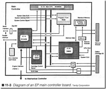
Symptom 1 The printer’s LCD shows a “CPU Error.” Some printer designs might show this error as a series of blinking LEDs, or a se quence of beeps. The CPU is the heart of your printer’s logical op eration. When you first start the printer, the CPU and its associated core logic (figure 11-3) is tested, much like the BIOS of
a computer will execute a self test. If the CPU fails to pass all of its test requirements, an error will be generated.
As you might imagine, a CPU failure is catastrophic; that is, the printer simply will not work without it. Start by turning off and un plugging the printer, then examine each of the connectors on the main controller. Each connector should be installed properly and completely. If problems persist, you will have to replace the CPU. Replacing the CPU can be either cheap or expensive depending on how it is mounted. If the CPU is socket-mounted on the main con troller, you can often just remove the old CPU and plug in a new one. However, if the CPU is soldered to the main controller board , you will have to desolder and resolder the CPU (if you have the proper surface-mount soldering tools), or replace the entire main controll er.
Symptom 2 The printer’s LCD shows a “ROM Checksum Error.” Your particular printer might use an error number (e.g., ER ROR 11) to represen t th e condition. As in a comput er, all of the print er’s on-board instru ctions and prog ramming are held in a ROM on the main controller board. It is the ROM that pro vides key instructions and data to the CPU for processing. When the printer starts, a checksum test is run on the ROM to verify the integrity of its contents. If the resulting checksum
does not match the checksum reference number stored in the ROM, an error is generated. You can see the “program/font ROM” in figure 11-3.
First, check to see that any supplemental font or option cartridges are installed properly; you might try removing the cartridge(s) to find if the problem disappears. If there are no option cartridges, or the problem persists, you must replace the ROM IC. In many cases, ROM ICs are socket-mounted devices because they must be programmed outside of the logic board’s assembly process. When this is the case, you might be able to replace the ROM IC directly. If the ROM IC is soldered to the main logic board (or a replace ment ROM IC is simply not available), you will have to replace the entire main logic board.
Symptom 3 The printer’s LCD shows a “RAM RJW Error,” a “Mem ory Error,” or other memory defect. Your particular printer might use an error number (e.g., ERROR 12 or ERROR 30) to represent the condition. Dynamic RAM (or DRAM) serves as the workspace for an EP printer. Where moving-carriage printers typically offer buffers of BKB or 16KB, the EP printer can easily offer 1MB or more; some high-end printers can accommodate 16MB or more. This volume of memory is necessary because the EP printer must be able to construct the data needed to form an entire page at a time. For an 8.511 x 1111 page at high resolutions, this can be a phe nomenal volume of data. Unfortunately, trouble in any part of the DRAM can adversely affect the image, especially PostScript im ages. Memory is tested when the printer is first initialized. Like PCs, the more memory that is installed, the longer it takes the printer to initialize. A typical test involves writing a known byte to each address, then reading those bytes back. If the read byte matches the written byte, the address is considered good; other wise, a RAM error is reported. You can see the default 1MB of DRAM in figure 11-3.
It is rare that a RAM error message will indicate the specific loca tion of the error, but you can easily isolate the fault to a bad mem ory module or the standard (resident) memory. Turn off and unplug the printer, then remove any expansion memory modules that might be installed. You might have to set jwnpers or DIP switches to tell the printer that memory has been removed. If the problem disappears, one or more of your expansion memory modules has failed. Try reinstalling one module at a time until the problem re occurs; the last module to be installed when the error surfaced is the faulty module. If the problem persists when memory modules are removed, you can be confident that the fault is in your resident memory. Although memory modules often take the form of SIMMs or other plug-in modules, resident RAM is typically hard-soldered to the main controller board. You might attempt to replace the RAM if you have the proper desoldering tools and replacement RAM ICs on hand. Otherwise, simply replace the main controller board.
Symptom 4 Your printer’s LCD shows a “Memory Overflow” er ror. Your particular printer might use an error code (e.g., ER ROR 20) to represent the condition. When data is sent from the computer to the printer, part of that data consists of “user information,” such as soft-fonts and macro commands. If the amount of “user information” exceeds the amount of RAM set aside for it, a “Memory Overflow” (or similar error) will be generated. While this error is not directly related to the image size or complexity, complex images typically carry a larger overhead of “user information,” so you might find that simpli fying the image can sometimes clear the problem even though the image itself is not really at fault. Generally speaking, you can eliminate this error by adding optional memory, or reduc ing the amount of data that must be downloaded to the printer (often a function of the application doing the printing).
Symptom 5 Your printer’s LCD shows a “Print Overrun” error. Your particular printer might use an error code (e.g., ERROR 21) to represent the condition. Unlike the last error, “print overrun” prob lems almost always indicate that the page to be printed is too com plicated for the printer; there is just not enough memory to hold all of the data required to form the image. To overcome this type of problem, try simplifying the image (e.g., use fewer fonts or try using solid shading instead of dithering). You might also try mak ing the printed area smaller. For example, instead of printing an image at 8 x 811, try printing it at 5 x 5″. The smaller image requires less raw data. The ideal way to correct this problem over the long term is to add memory to the printer.
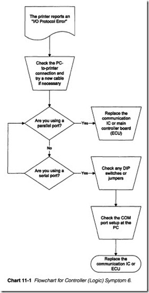
Symptom 6 The printer reports an “I/O Protocol Error.” Refer to Chart 11-1. Your particular printer might use an error code (e.g., ERROR 22) to represent the condition. This is a communication fault. The term protocol basically means agreement or rules. So when a protocol error arises, it suggests that the computer and printer are not communicating “by the rules.” The most blatant protocol error is connecting a serial port to a parallel printer, or a parallel port to a serial printer, but this is an extremely rare over
sight, and one that usually only occurs when a printer is first installed. Protocol errors among parallel ports are also very rare because parallel port operation is very well defined with hand shaking designed right into the signal layout. The most likely pro tocol problems can arise with serial communication; there are so many variables in the serial process that must be matched be tween the printer and computer, that even the slightest error can cause problems.
Start by checking the connections between the computer and printer. See that the communication link is parallel-to-parallel or serial-to-serial. Also try a new, high-quality cable (serial or parallel as appropriate) between the printer and computer. When parallel communication is being used, a protocol error suggests a failure in the communication interface IC (IClO in figure 11-3). You can try replacing the communication IC, or replace the main controller board entirely. When serial communication is being used, you should examine any DIP switches or jumpers inside the printer. Check to see that the communication speed and framing bits are all set as expected, then see that the corresponding COM port in the PC is configured similarly (through the printing application or the Wmdows Printer Control Panel). If problems persist, even
when the serial communication link is set properly, suspect trouble in the communication interface IC. You can try replacing the communication IC, or replace the main controller outright.
Symptom 7 The image is composed of “garbage” and disassociated symbols. Your printer might also generate a “Parity/Framing Er ror,” or use an error code (e.g., ERROR 40) to represent the con dition. This error indicates that there is a problem with serial data framing. As detailed in Chapter 9, serial data must be “framed” with the proper number of start, data, parity, and stop bits. These bits must be set the same way at the printer and the computer’s COM port. If either end of the communication link is set improp erly, data passed from the computer to the printer will be misin terpreted (resulting in highly distorted printout). Check the printer first and note any DIP switch or jumper settings that affect the data frame. Next, check the COM port settings at the computer (under the printing application or the Wmdows Printer Control Panel). The COM port’s start, data, parity, and stop bit configura tion should all match the printer’s settings. Ifnot, adjust either the COM port parameters or the printer DIP switch settings so that both ends of the communication link are set the same way. If prob lems persist, there might be a fault in the printer’s communication IC (e.g., IClO in flgure 11-3). You might try replacing the IC, or you might replace the main controller entirely.
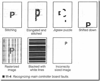
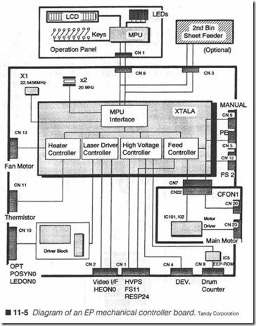
Symptom 8 The image appears “stitched .” Stitching is an image distortion where points in the image appear to have been “pulled” in the horizontal direction (typically to the right). Figure 11-4 il lustrates the “stitching” effect, along with some manif estations of other controller errors. Images are formed by scanning a laser beam repetitively across the drum. Pixels are formed by turning the laser beam on and off while scanning, a function performed by the mechanical controller board, as shown in figure 11-5. If there is an intermittent fault in the mechanical controller logic, beam modulation might fail during one or more scanning passes, result ing in random “pulls” in the image.
Start your examination by checking all of the cables between the laser/scanner assembly and the mechanical controller. Loose wiring might result in intermittent laser fire. Tum off and unplug the printer, then try removing and reinstalling each of the connectors. Check any other wiring on the mechanical controller as well. If problems persist, chances are very good that the mechanical con troller has failed. You might attempt to troubleshoot the mechani cal controller, as described in Chapter 9, but it is often more efficient to simply replace the mechanical controller board outright. If a new mechanical controller fails to resolve the problem,replace the laser/scanner assembly.
Symptom 9 The image appears elongated and “stitched.” This is a variation of Symptom 8. Not only is the laser beam misfiring inter mittently, but the image is being “stretched” along the page. Under most circumstances, there has been a logic failure on the mechan ical controller. Before you attempt work on the controller, how ever, try reseating each of the connectors on the mechanical controller. Be sure to tum off and l.Ulplug the printer before fid dling with any connectors. If problems persist, there is a serious fault in the printer’s ECU. You might attempt to troubleshoot the ECU as outlined in Chapter 9, but this type of fault can be very difficult to track down. As a result, it is often better to try replacing the mechanical controller board first. If that fails to correct the problem, try a new main logic board. If your particular printer de sign integrates all of the logic and controlling circuitry on a single ECU board, replace that board outright.
Symptom 10 Portions of the image are disassociated like a jigsaw puzzle. Of all the controller failures, this is perhaps one of the most perplexing. You might notice that some elements of the printed image are fme, but other Oarger) areas of print seem jumbled around. To make matters worse, the problem is often intermittent, so some printed pages might appear fine. Under most circum stances, there has been a logic failure on the main controller board. Before you attempt work on the main controller, however, try reseating each of the connectors on the main and mechanical controller boards. Be sure to turn off and unplug the printer be fore working with any connectors. If problems persist, there is a serious fault in the printer’s ECU. You might attempt to trou bleshoot the ECU as outlined in Chapter 9, but this type of “jigsaw puzzle” operation can be very difficult to track down. As a result, it is often better to try replacing the main controller board first. If that fails to correct the problem, try a new mechanical controller board. If your particular printer design integrates all of the logic and controlling circuitry on a single ECU board, replace that board outright.
Symptom 11 The image appears to be shifted down very signifi cantly. You can see this type of problem illustrated in figure 11-4. At first glance, you might be tempted to think that this is a regis tration problem (and cannot be ruled out), but it is also possible that fault on the mechanical controller (probably the “feed con trol” circuit as in figure 11-5) is passing the page through far too soon before the developed image is aligned. Chances are that the pick-up and registration mechanics are working correctly; other wise, the page would likely lose its top margin or appear smudged. When the top margin is excessive, suspect a logic fault. Specifi cally, you should suspect that a logic error is firing the registration system too soon after a printing cycle starts. You should address this type of problem by troubleshooting or replacing the mechani cal controller board.
Symptom 12 The image appears “rasterized” with no intelligible in formation. A “rasterized” image is a complete distortion; there is rarely any discernible information in the printed page. Instead, the image is composed of broken horizontal lines, such as in figure 11-4. The trick with this type of fault is that it is not always easy to
determine the problem origin. Turn off and unplug the printer. Open the printer and check each cable and wiring harness at the controller board(s) and laser/scanning assembly. Try reseating each of the connectors. If the problem persists, the fault is almost certainly in the main controller board. Chapter 9 offers some es sential ECU troubleshooting information, but this type of logical troubleshooting can be extremely challenging and time-consum ing. So it is often easier to just replace the main controller board and retest the printer. If a new controller board fails to correct the problem, you should troubleshoot or replace the mechanical con troller board.
Symptom 13 The image is blacked out with white horizontal lines. This type of problem creates a page that is blacked out except for a series of white horizontal bars, and will typically eradicate any discernible image on the page. As it turns out, connector problems can readily cause this type of problem, so start your examination there. Turn off and unplug the printer, then check the wiring har nesses and reseat each connector on the main and mechanical controller boards. Be extremely careful to replace each connector carefully, and avoid bending any of the connector pins.If the problem continues, your fault is likely to be in the main con troller board. Chapter 9 offers some essential ECU troubleshoot ing information, but this type of logical troubleshooting can be extremely challenging and time-consuming, especially under these symptoms. So it is often easier to just replace the main con troller board and retest the printer. If a new controller board fails to correct the problem, you should troubleshoot or replace the mechanical controller board.
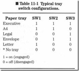
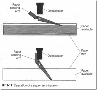
Symptom 14 The image is incorrectly sized along the vertical axis. Ideally, an image should be sized according to the size of whatever paper tray is installed. When the image size is signif icantly smaller than expected, you should first check to see that the proper paper tray is installed, and that the printing application is set to use the correct paper size (especially un der Windows). If everything is configured properly, you should examine the paper tray sensors as described in Chapter 9. Re place any defective tray sensor microswitches. If problems persist, you should also inspect any wiring harnesses and con nectors at the mechanical controller. Loose or defective wiring can cause erroneous page sizing. If the connectors check properly, you should suspect a logical problem in the mechan ical controller board. You might attempt to troubleshoot the
mechanical controller if you wish, or you might simply choose to replace the mechanical controller outright. If that should fail to resolve the problem, try a new main controller board.
Registration symptoms
The “registration” process involves picking up a sheet of paper and positioning it for use. AB a result, any problems in the paper tray, pick-up roller, separation pad, registration rollers, or the related drive train can result in any one of the following problems. Regis tration problems are quite common, especially in older printers, where age and wear can affect the rollers, gears, and critical me chanical spacing. In very mild cases, you might be able to correct a registration problem with careful cleaning and a bit of readjust ment. For most situations, however, you will need to replace a de fective mechanical assembly, or a failing electromechanical device (such as a clutch).
Symptoms
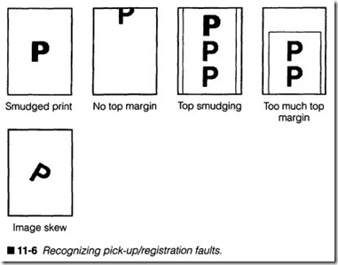
Symptom 1 The print contains lines of print, usually in the lower half of the page, that appear smudged. You can see a simple ex ample of the problem in flgure 11-6. This symptom is almost al ways the result of a problem with your registration rollers. Uneven wear can allow the registration rollers to grip the page frrrnly at one point, then loosely at another point. When the grip tightens, the page jerks forward just a fraction, but enough to smudge (or blur) the print at that point. Turn off and unplug the printer, then expose the registration assembly and examine it closely. Look for any accumulations of debris or obstructions that might force the registration rollers apart at different points. Remove any obstructions and try cleaning the roller pair. Exam ine the registration drive train and look for any gears that might be damaged or obstructed. Clean the drive train and replace any damaged gears. If the problem persists, you should consider re placing the registration assembly.
Symptom 2 There is no apparent top margin. The image might run off the top of the page, as in flgure 11-6. In just about every case. There is a fault in the pick-up assembly. AB a consequence, the page is not being passed to the registration assembly in time to be aligned with the leading edge of the drum image, so the image ap pears cut off at the page top. Start by examining your paper tray. Make sure that the “lift mechanism” is not jammed or otherwise in terfering with paper leaving the tray. If you’re not sure, try a different paper tray. Also consider your paper itself. Unusually light or specially coated papers might simply not be picked up properly. Try a standard 20-lb. bond xerography-grade paper. If problems persist at this point, chances are that your pick-up assembly is fail ing. Turn off and unplug the printer, then examine your pick-up system closely. Check for any accumulations of debris or obstruc tions that might interfere with the pick-up sequence. Remove any obstructions, then clean the pick-up roller and separation pad. Also examine the pick-up drive train and clutch. Any jammed or damaged gears should be replaced. If the solenoid clutch is stick ing or failing, you should replace the solenoid clutch or clutch PC board. If that fails to resolve the problem, you will have little alter native but to replace the pick-up assembly and separation pad.
Symptom 3 There is pronounced smudging at the top of the image (generally near the top margin). This symptom suggests that the registration assembly is failing, or it has not been installed cor rectly. Turn off and unplug the printer, then expose the registra tion system. Carefully inspect the system to see that the rollers and drive drain are installed properly. Try reinstalling the registra tion assembly. If problems persist, try a new registration assembly.
Symptom 4 There is too much margin space on top of the image. When there is excessive margin space at the top of the image, it generally indicates that the paper has been allowed into the IFS too soon; paper is traveling through the printer before the drum image was ready. This fault is usually related to the registration roller clutch. You see, the registration rollers are supposed to hold the page until the drum image is aligned properly. This means that the registrations rollers must be engaged or disengaged as required, typically through a clutch mechanism. If the clutch is jammed in the engaged position, the registration rollers will always run (pass ing each new page through inunediately). Turn off and unplug the printer, then examine your registration clutch closely. If the clutch is jammed, try to free it and clean surrounding mechanics to re move any accumulations of debris. If the clutch fails to re-engage or remains jammed again, replace the registration clutch entirely, or replace the clutch solenoid PC board.
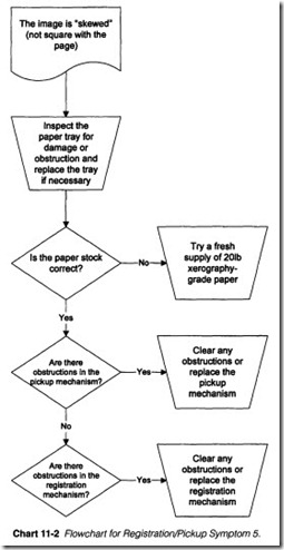
Symptom 5 The image is “skewed” (not square with the page). Re fer to Chart 11-2. Skew occurs when the page is passed through the printer at an angle (rather than straight). Typically, paper must enter the printer straight because of the paper tray, so the page must shift due to a mechanical problem. In actual practice, however, a loose or bent paper guide tab can often shift the paper as it enters the printer. Start your examination by checking the pa per tray, specifically the paper cassette guide tab. If the tab is loose or bent, replace it or try a new paper tray. If the paper tray is intact, consider the paper itself. Unusually light or specially coated papers can skew in the pick-up and registration mechanics. If you are using an unusual paper, try some standard 20-lb. xerography grade paper. If the problem should continue, tum off and unplug the printer, then examine the pick-up and registration mechanics. Check for obstructions, or any accumulations of foreign matter that might interfere with the paper path and cause the page to skew. If there is nothing conclusive, try replacing the pick-up as sembly and separation pad, then the registration assembly (in that order).
Laser/scanner problems
A laser beam must be modulated (turned on and off correspond ing to the presence or absence of a dot) and scarmed across the conditioned drum. Both modulation and scanning must take place at a fairly high rate in order to form an image, up to 12 pages per minute and more. However, the process of writing with a laser beam is not a simple task, as you see in figure 11-7. Variations in laser output power (often due to age), variations inpolygon motor speed (also due to age and wear), and the accumulation of dust
and debris on the polygon mirror and other optical components will all have an adverse impact on the fmal image. Faults can even creep into the laser sensor and affect beam detection and align ment. EP printer designers responded to the problems associated with such a delicate assembly by placing all of the laser, control, and scanning components into a single “laser/scanner” assembly. Today, the laser/scanner is an easily replaceable module, and that is how we will treat it.
Symptoms
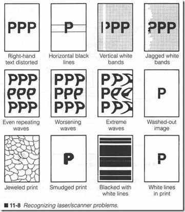
Symptom 1 Right-hand text appears missing or distorted. Figure 11-8 illustrates a typical example. In many cases, this is simply a manifestation of low toner in your EP/toner cartridge. If any area of the development roller receives insufficient toner, it will result in very light or missing image areas. Turn off and unplug the printer, remove the EP/toner cartridge, and redistribute the toner. Follow your manufacturer’s recommendations for toner redistri bution. If you see an improvement in image quality (at least tem porarily), replace the EP/toner cartridge.
Examine the shock mountings that support your laser/scanner as sembly. If the laser/scanner assembly is loose or not mounted cor rectly, scan lines might not be delivered to the proper drum locations. Try remounting the laser/scanner assembly. If the problem persists, replace the writing mechanism entirely. Ifyou are using a laser writing mechanism, pay special attention to the installation and alignment of the laser beam sensor.
Symptom 2 You encounter horizontal black lines spaced rand omly through the prin t. Remember that black areas are the result of light striking the drum. Ifyour prin ter uses a laser/scanner assem bly, a defective or improperly seated beam detector could send false scan timing signals to the main logic. The laser would then mak e its scan line while main logic waits to send its data. At the beginning of each scan cycle, the laser beam strik es a detector. The detector carries laser light through an optical fiber to a circuit,
which converts light into an electronic logic signal that is compat ible with the mechanical controller’s logic. Circuitry interprets this “beam detect signal” and knows the polygon mirror is properly aligned to begin a new scan. The mechanical controller then mod ulates the laser beam on and off corresponding to the presence or absence of dots in the scan line.
Positioning and alignment are critical here. If the beam detector is misaligned or loose, the printer’s motor vibrations might cause the detector to occasionally miss the beam. Printer circuitry responds to this by activating the laser full-duty in an effort to synchronize itself again. Reseat the laser/scanner assembly, or try reseating the beam detector and optical fiber. If the problem persists, try re placing the beam detector and cable, or replace the laser/scanner unit outright.
Symptom 3 Your printer’s LCD reports a “polygon motor synchro nization error.” The printer might also display an error code (e.g., ERROR 31) to represent the condition. The polygon mirror is the heart of the laser scanning system. The motor’s speed must be ab solutely steady. If the motor fails to rotate, or fails to synchronize at a constant rate within a few seconds of power-up, scanning will fail. In early EP printers, the polygon motor and mirror were im plemented as discrete devices. In today’s EP printers, however, the laser, scanner motor, and polygon mirror are all integrated into a replaceable laser/scanner assembly. When a scanner error is re ported, you should first shut down the entire printer, let it rest for several minutes, then turn it back on to see if the error clears. If the fault persists, your best course is simply to replace the laser/ scanner assembly entirely.
Symptom 4 There are one or more vertical white bands in the im age. At first glance, this symptom might appear to be a problem with the transfer corona. However, you will notice that the white band(s) appearing here are thick and well-defined (and cleaning the transfer corona will have no effect). A hard white band such as this suggests that the laser beam (or LED light) is being blocked. This is not as uncommon as you might imagine. Dust, foreign mat ter, and debris can accumulate on the focusing lens and obstruct the light path. It is also possible that there is a chip or scratch in the lens.
Turn off and unplug the printer. Start your examination by check ing and cleaning the transfer corona; the trouble is probably not here, but perform a quick check just to eliminate that possibility. If the transfer corona should prove dirty, certainly retest the printer.
If the problem persists, expose the “beam-to-drum” mirror and fo cusing lens, and examine both closely. Look for dust, dirt, toner, paper fragments, or any other foreign matter that might have ac cumulated on the optics. If you find foreign matter, you should not just blow it out with compressed air; it will make a mess, and the dust will eventually resettle somewhere else. Take the nozzle of a vacuum cleaner and hold it i proximity of the optical area, then blow the optics clean with a canister of compressed air. This way, the foreign matter loosened by the compressed air will be vacu umed away rather than resettle in the printer. The key idea to re member here is do not touch the optics.
For stains or stubborn debris, clean the afflicted optics gently with a high-quality lens cleaner fluid and wipes from any photography store. Be very careful not to dislodge the “beam-to-drum” mirror or lens from its mounting. Never blow on a lens or mirror yourself; breath vapor and particles can condense and dry on a lens to cause even more problems in the future. Allow any cleaner residue to dry completely before reassembling and retesting the printer.
If the problem should persist, suspect a problem with the laser/ scanner assembly. There might be some foreign matter on the laser aperture that blocks the scanned beam as it leaves the scan ner. Check the laser/scanner’s beam aperture and clean away any foreign matter. If the material is inside the laser/scanner assembly, it should be replaced.
Symptom 5 There is a white jagged band in the image. This symp tom is similar in nature to the previous symptom; foreign matter is interfering with the laser beam path. The major difference is that instead of a solid white band, you see a random jagged white band. A major difference, however, is that the obstruction is random (drifting in and out of the laser path unpredictably). This suggests that you are dealing with a loose obstruction, such as a paper frag ment, which is able to move freely. Turn off and unplug the printer, then check for obstructions around the transfer corona. While the transfer corona itself is probably not fouled, a paper fragment stuck on the monofilament line can flutter back and forth resulting in the same jagged appearance.
Next, check the optical path for any loose material that can ob struct the laser beam. Be particularly concerned with paper fragments or peeling labels. Fortunately, such obstructions are relatively easy to spot and remove. When removing an obstruc tion, be careful to avoid scratching or moving any of the opti cal components. If the problem persists, you might have an obstruction inside of the laser/scanner assembly, so it should be replaced.
Symptom 6 There are repetitive waves in the image. You can see a simple example of this fault in flgure 11-8. All of the image ele ments are printed, but there is a regular “wave” in the image. This kind of distortion is typically referred to as scanner modulation, where scanner speed oscillates up and down just a bit during the scanning process. In virtually all cases, the fault lies in your laser/scanner assembly. Tum off and unplug the printer, then try reseating the cables and wiring harnesses connected to the laser/ scanner unit. Try the printer again. Ifproblems persist, replace the laser/scanner assembly.
Symptom 7 There are worsening waves in the image. This type of problem is a variation of the “scanner modulation” fault, shown in the previous symptom. In this case, however, the modulation is relatively mild on the left side of the page, and gradually increases in magnitude toward the right side. These “worsening waves” can take several forms, as shown in figure 11-8; typical manifestations can be heavy or light. Regardless of the modulation intensity, all of these symptoms can often be traced to a connector problem at the laser/scanner assembly. Tum off and unplug the printer, then care fully reseat each connector and wiring harness between the laser/scanner unit and the mechanical controller board. If prob lems persist, replace the laser/scanner assembly.
Symptom 8 The image appears washed out; there is little or no in telligible information in the image. ‘J.Ypically, you will see random dots appearing over the page, but there are not enough dots to form a coherent image. Light images might suggest a problem with the high-voltage power supply or the transfer system, but in many such circumstances, some hint of an image is visible. You might also suspect the toner supply, but toner that is too low to form an image will register a “low toner” error. Still, a quick check is always advisable. Remove the EP cartridge and try redistributing the toner, then try darkening the print density wheel setting. If the image im proves, check the EP/toner cartridge and suspect the HVPS. Other wise, you should suspect a failure at the laser diode itself. Although solid-state lasers tend to run for long periods with little real degradation in power, an aging laser diode might produce enough energy to satisfy the laser sensor, but not nearly enough to discharge the EP drum. Try replacing the laser/scanner assembly.
Symptom 9 The print appears “jeweled.” You can see this kind or print in figure 11-8. This is caused when the laser beam is totally unable to synchronize with the printer; the laser sensor is failing to detect the beam. In many cases, the fiber-optic cable carrying the laser signal has been detached or broken. When the optical cable is a stand-alone component, it is a relatively easy matter to replace the cable and sensor. If the cable and sensor are integrated into the laser/scanner assembly, your best course is to reseat the cables and wiring harnesses between the laser/scanner and the mechani cal controller board. If problems persist, replace the laser/scanner assembly outright.
Symptom 10 You see regular “smudging” in the print. When dirt, dust, and other foreign matter accumulate on the “beam-to-drum” mirror or compensating lens, they tend to block laser light at those points, resulting in vertical white bars or lines down the image. However, mild accumulations of dust or debris that might not be heavy enough to block laser light might be enough to “scatter” some of the light. This “scattered light” spreads like shrapnel re sulting in unwanted exposures. Because each point of exposure becomes dark, this often manifests itself as a “dirty” or “smudged” appearance in the print. Your best course is to clean the printer’s optical deck. Turn off and unplug the printer, then expose the optical area. Place the nozzle from your vacuum cleaner in the immediate area, and blow away any dust and debris with a can of photography-grade compressed air. Do not attempt to vacuum inside of the printer! Just let it remove any airborne contaminants dislodged by the compressed air.
Symptom 11 The print is blacked out with white horizontal lines. In order to modulate the laser beam to form dots, the data must be synchronized with the position of the laser beam. This synchro nization is accomplished by the beam detector, which is typically located in the contemporary laser/scanner assembly. If the detec tor fails to detect the laser beam, it will fire full-duty in an attempt to reestablish synchronization. When the beam fires, it will pro duce a black line across the page. Multiple subsequent black lines will effectively black-out the image. The white gaps occur if the beam is sensed, or if a time-out/retry period has elapsed. In most cases, the beam sensor in the laser/scanner assembly has failed or become intermittent. ‘fum off and unplug the printer, then try re seating each of the cables from the laser/scanner. If the problem persists, your best course is simply to replace the laser/scanner as sembly entirely.
Symptom 12 The image forms correctly except for random white gaps that appear horizontally across the page. This is another manifestation of trouble in the laser beam detection process. A kink in the fiber-optic cable can result in intermittent losses of laser power. In older printers with a discrete fiber-optic cable, it was a simple matter to replace the cable outright. Now that beam detection is accomplished in the laser/scanner assembly itself, your best course is simply to replace the unit outright.
Drive or transmission problems
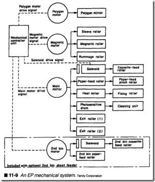
With so much emphasis placed on the key electronic and mechan ical subassemblies of an EP printer, it can be easy to forget that each of those mechanical assemblies are coupled together with a comprehensive drive train of motors, gears, and (sometimes) pul leys. A failure, even an intermittent, at any point in the drive or transmission will have some serious consequences in the printed image. Figure 11-9 outlines the printer’s mechanical system.
The mechanical controller (sometimes referred to as the de con troller) starts the main motor. Once the main motor starts, a gear train will operate the EP drum, the transfer (or feed) roller(s), and the fusing rollers. In some designs, the main motor will also operate a set of exit rollers that direct the page to an output tray. Of course, there must also be a provision to pick up and register each page, but those assemblies cannot run full-duty; instead, they must be switched on and off at the proper time. To accomplish this timing, a solenoid-driven clutch (marked “Solenoid”) is added to the pick-up roller and registration roller assemblies. For the sys tem in figure 11-9, a separate motor (marked “Magnetic motor”) is used to drive the development system.
Symptoms
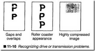
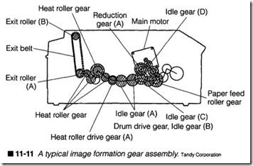
Symptom 1 There are gaps and overlaps in the print. Figure 11-10 shows you an example of this symptom. The problem here is a slip ping gear or failing drive motor. Unfortunately, this is not a simple problem to spot; gear assemblies such as the one in figure 11-11 are generally quite fine, and an intermittent gear movement can easily go unnoticed. Start with a careful inspection of the gear train. Make sure that all gears are attached and meshed securely. It is not uncommon for older gear assemblies to loosen with wear. Also check that the main motor is mounted securely and meshed properly with other gears. Be especially careful to check for obstructions or foreign matter that might be lodged in the gear train. Finally, you will need to check each gear for broken teeth, which is a time-consuming and tedious process, but it is preferable to dis mantling the entire drive train. A high-intensity pen light will help to highlight broken gear teeth. Replace any gears that might be damaged. If the problem persists and the drive train is flawless, try replacing the main motor assembly.
Symptom 2 The print has a “roller-coaster” appearance. This type of roller coaster distortion is typically the result of a fault in the gear train. Start with a careful inspection of the gear train. Make sure that all gears are attached and meshed securely. It is not un common for older gear assemblies to loosen with wear. Also check that the main motor is mounted securely and meshed properly with other gears. Be especially careful to check for obstructions or
foreign matter that might be lodged in the gear train. Finally, you will need to check each gear for broken teeth, which is a time-con suming and tedious process, but it is preferable to dismantling the entire drive train. A high-intensity pen light will help to highlight broken gear teeth. Replace any gears that might be damaged.
Symptom 3 The image is highly compressed in the vertical axis. A highly compressed image can indicate a failing main motor, espe cially when the amount of “compression” varies randomly from page to page. Because the main motor is responsible for driving the entire system, a fault can interrupt the page transport. Check the main motor to see that it is mounted securely to the frame and meshed properly with other gears. Also check the connector and wiring harness at the main motor and mechanical controller board to be sure that everything is attached properly. If problems persist, try replacing the main motor. If that fails to correct the problem, replace the mechanical controller board.
HVPS problems
High voltage is the key to the electrophotographic process. Huge electrical charges must be established in order to condition the EP drum, develop a latent image, and transfer that image to a page. An HVPS for the classical “SX-type” engine develops
-6,000, +6,000, and -600 V. The newer “CX-type” engine requires far less voltage (-1,000, +1,000, and -400 V). Still, high voltages impose some important demands on the power supply and its as sociated wiring. First, high-voltage supplies require precise com ponent values that are rated for high-voltage operation. While ordinary circuits might easily tolerate a “close” component value, HV supplies demand direct replacements. Installing a “close” value (or a part with a loose tolerance) in an HVPS can throw the output(s) way off. The other factor to consider is the wiring. Most commercial wire is only insulated to 600 V or so; higher voltages can jump the inexpensive commercial insulation and arc or short circuit; they can even electrocute you. So HVPS wiring harnesses and connectors are specially designed to operate safely at high voltages.
As a technician, these factors present some special problems. Re placement components are expensive and often difficult to find.
Installing those components can be tedious and time-consuming.
And even when things are working perfectly, you can not measure the outputs directly without specialized test leads and equipment.
When all of this is taken into account, it is almost always prefer able to replace a suspected HVPS outright rather than attempt to troubleshoot it.
Symptoms
Symptom 1 Your printer’s LCD displays a “high-voltage error.” The printer might also use an error code (e.g., ERROR 35) to repre sent the condition. This indicates that one or more outputs from the HVPS are low or absent. The preferred technique is to replace the HVPS outright. Before replacing an HVPS, turn off and unplug the printer, and allow at least 15 minutes for charges in the HVPS to dissipate. When replacing the HVPS, be very careful to route any wiring away from logic circuitry, and pay close attention when installing new connectors. It is also important that you bolt the new HVPS securely into place; this ensures proper grounding.
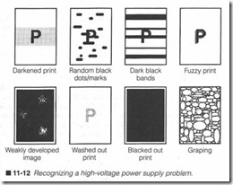
Symptom 2 The image is visible, but the print out is darkened. You can see this type of symptom in figure 11-12. In order for an image
to be developed, the EP drwn must be discharged. This can also happen if the primary corona fails to place a conditioning charge on the drum. At first, you might suspect that the -6,000-V somce is low, but in actual practice, this type of symptom is typically the result of bad HVPS grounding. Turn off and unplug the printer, then allow at least 15minutes for the HVPS to discharge. Open the prin ter and inspect the mounting bolts holding the HVPS in place. Chances are that you’ll fmd one or more grounding screws loose. Gently tighten each of the mounting/grounding hardware (you don’t want to strip any of the mounting holes). Secme the printer and retest.
Symptom 3 There are random black splotches in the image. Gen erally, the image will appear, but it will contain a series of small black marks spaced randomly throughout the page. This type of image problem suggests that the HVPS is arcing internally (and is probably close to failme). Turn off and unplug the printer, then al low at least 15minutes for charges in the HVPS to dissipate. Check the high-voltage connectors and high-volt age wiring harness. Try reseating the connectors to check for failing contacts. If problems persist, replace the HVPS.
Symptom 4 There is “graping” in the image. The “graping” effect places small, dark, oval-shaped marks on the page, usually along one side of the page. Graping is often due to a short-circuit in the primary corona HV connector; HV is arcing out. Turn off and un plug the printer, then allow at least 15 minutes for any charges in the HVPS to dissipate. Inspect the primary corona wiring, and check for any shorts along the corona, or along the HV lead from the HVPS. Try reseating the HV connectors and wiring. If prob lems persist, replace the primary corona HV lead (if possible); oth erwise, replace the HVPS.
Symptom 5 The image appears, but it contains heavy black bands. You can see an example of this in figure 11-12. Although this symptom might look quite different from Symptom 2, it is really quite similar. If the HVPS ground is loose, the image can be darkened, but if the HVPS ground is simply intermittent, por tions of the image might be exposed just fine. As the grounding cuts out, however, primary voltage fails, and the lack of condi tioning voltage causes a black band to form. When the ground kicks in again, the image formation resumes, and so on. Turn off and unplug the printer, and allow at least 15 minutes for the HVPS to discharge. Gently tighten or reseat each of the ground ing screws holding the HVPS in place (be careful not to strip the threaded holes). Also check the HV wiring harness to see that it is not crimped or shorted by other assemblies. If problems persist, replace the HVPS.
Symptom 6 The image appears fuzzy, letters and graphics appear “smudged” or “out of focus.” This type of problem suggests a fault in the ac bias voltage. Toner is heavily attracted to the exposed drum. When toner jumps to the drum, some toner lands in nonex posed areas near the exposed points. By using an ac developer bias, the developer voltage varies up and down. As developer volt age increases, more toner is passed to the exposed drum areas. As developer voltage decreases, toner is pulled back from the nonex posed drum areas. This action increases image contrast while cleaning up any “collateral” toner that might have landed improp erly. If the ac component of your developer voltage fails, that con trast-enhancing feature will go away, resulting in fuzzy print. Because developer voltage is generated in the HVPS, try replacing the HVPS outright.
Symptom 7 There are weakly developed areas in the image. The image appears, but various areas of the image are unusually light. This can be attributed to moisture in the paper. Try a supply of fresh, dry paper in the paper cassette. Also make sure that the pa per does not have a specialized coating. If the problem persists, you should suspect that the HVPS is weak and nearing failure. For a symptom such as this, your best course is usually just to replace the HVPS outright. Be sure to turn off and unplug the printer, and allow at least 15 minutes for the HVPS to discharge before at tempting replacement.
Symptom 8 The image appears washed out. This type of symptom can often be the result of several causes. Before proceeding, check the print density wheel and try increasing the density setting. If problems continue, check your paper supply. Specially or chemi cally coated papers might not transfer very well. If the problem continues, you should suspect that the transfer voltage is weak or absent, or the primary grid voltage might be failing. In either case, you should replace the HVPS. Be sure to turn off and unplug the printer, and allow at least 15 minutes for the HVPS to discharge before attempting replacement.
Symptom 9 The page is blacked out. This symptom suggests that the primary corona voltage has failed. Without a conditioning charge, the EP drum will remain completely discharged; this will attract full toner, which will result in a black page. Before at tempting to replace the HVPS, check the primary corona to see that it is still intact, and check the wiring between the primary corona and the HVPS. If the primary corona is damaged, replace the EP/toner cartridge; otherwise, replace the HVPS. Be sure to turn off and unplug the printer, and allow at least 15 minutes for the HVPS to discharge before attempting replacement.
Fusing assembly problems
The fusing assembly is another focal point for many printer prob lems. In order to fix toner to the page surface, a combination of heat and pressure is applied with a set of fusing rollers. The upper roller provides heat while the lower roller provides pressure. In or der for the fusing assembly to work properly, there are several fac tors that must be in place. First, the heating roller must reach and maintain a constant temperature; that temperature must be con sistent across the roller’s surface. Second, pressure must be con stant all the way across the two rollers, so the two rollers must be aligned properly. Third, not all melted toner will stick to the page; some will adhere to the heating roller. So there must be some pro vision for cleaning the heating roller. Finally, there must be a reli able method for protecting the printer from overheating.
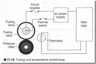
The fusing unit design shown in figure 11-13 addresses these con cerns. Heat is generated by a bar heater or a long quartz lamp mounted inside of the upper fusing roller. Power to operate the heater is provided from the de power supply (typically 24 V) . A separate thermistor in the roller changes resistance versus tern perature, so it acts as a temperature detector. The thermist or’s re sistance is measured by a circuit on the mechanical controller board, which in turn , modulates the power feeding the heater. This process “closes the loop” to achieve a stable operating tem perature. If a failure should occur that allows the heater to run continu ously, a thermal fuse will open and cut off voltage to the heater. Although figure 11-13 does not show it, the upper and lower fusing rollers are held together with torsion springs; the springs keep both rollers together with the right amount of corn pression, and can adjust for slight variations in paper weight and system wear. Toner that sticks to the upper fusing roller can trans fer off the roller elsewhere on the page, resulting in a “speckled” appearance. Therefore, the upper roller is coated with Teflon to reduce sticking, and a cleaning pad rubs any toner off the roller. You will find that temperatur e, alignment , and cleaning problems are some of the most frequent fusing troubles.
Symptoms
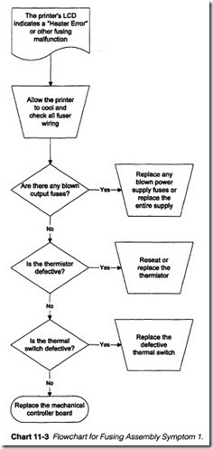
Symptom 1 The printer’s LCD indicates a “Heater Error” or other type of fusing temperature malfunction. Refer to Chart 11-3. Your particular printer might use an error number (e.g., ERROR 32) to represent the condition. Fusing is integral to the success ful operation of any EP printer. Toner that is not fused successfully remains a powder or crust that can flake or rub off onto your hands or other pages. Mechanical controller logic inter prets the temperature signal developed by the thermistor and modulates power to the quartz lamp. Three conditions will gen erate a fusing malfunction error: fusing roller temperature falls below about 140°C; fusing roller temperature climbs above 230°C; or fusing roller temperature does not reach 165°C in 90 seconds after the printer is powered up. Your particular printer might use slightly different temperature and timing parameters. Also note that a fusing error will often remain with a printer for 10 minutes or so after it is powered down, so be sure to allow plenty of time for the system to cool before examining the fus ing system.
Begin by examining the installation of your fusing assembly. Check to see that all wiring and connectors are tight and seated properly. The quartz heater power supply is often equipped with a fuse or circuit breaker that protects the printer (this is not the thermal switch shown in figure 11-13). If this fuse or circuit breaker is open, replace your fuse or reset your circuit breaker, then retest the printer. Remember to clear the error, or allow enough time for the error to clear by itself. If the fuse or breaker trips again during retest, you have a serious short circuit in your fusing assembly or power supply. You can attempt to isolate the short circuit, or simply replace your suspected assemblies (fusing assembly first, then the de power supply).
Turn off and unplug the printer, allow it to cool, and check your temperature sensing thermistor by measuring its resistance with a multimeter. At room temperature, the thermistor should read about 1kn (depending on the particular thermistor). If the printer has been at running temperature, thermistor resistance might be much lower. If the thermistor appears open or shorted, replace it with an exact replacement part and retest the printer.
A thermal switch (sometimes called a thermoprotector) is added in series with the fusing lamp. If a thermistor or main logic failure should allow temperature to climb out of control, the thermal switch will open and break the circuit once it senses temperatures over its preset threshold. This protects the printer from severe damage and possibly a fire hazard. Unplug the printer, disconnect the thermal switch from the fusing lamp circuit, and measure its continuity with a multimeter. The switch should normally be closed. If you fmd an open switch, it should be replaced. Check the quartz lamp next by measuring continuity across the bulb itself. If you read an open circuit, replace the quartz lamp (or the entire fusing assembly). Be sure to secure any disconnected wires. If the printer still does not reach its desired temperature, or continu ously opens the thermal switch, troubleshoot your thermistor sig nal conditioning circuit and the fusing lamp control signal from the mechanical controller, or replace the mechanical controller board entirely.
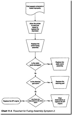
Symptom 2 Print appears smeared or fused improperly. Refer to Chart 11-4. Temperature and pressure are two key variables of the EP printing process. Toner must be melted and bonded to a page in order to fix an image permanently. If fusing tem perature or roller pressure is too low during the fusing opera tion, toner might remain in its powder form. Resulting images can be smeared or smudged with a touch. You can run the PRINTERS fusing test to check fusing quality by running a se ries of continuous prints. Place the first and last printout on a firm surface and rub both surfaces with your fingertips. No smearing should occur. If your fusing level varies between pages (one page might smear while another might not), clean the thermistor temperature sensor and repeat this test. Re member to wait 10 minutes or so before working on the fusing
assembly. If fusing performance does not improve, replace the thermistor and troubleshoot its signal conditioning circuit at
the mechanical controller. If smearing persists, replace the fusing assembly and cleaning pad.
Static teeth just beyond your transfer corona are used to dis charge the paper once toner has been attracted away from the EP drum. This helps paper to clear the drum without being attracted to it. An even charge is needed to discharge paper evenly, other wise, some portions of the page might retain a local charge. As pa per moves toward the fusing assembly, remaining charge forces might shift some toner resulting in an image that does not smear to the touch, but has a smeared or pulled appearance. Examine the static discharge comb once the printer is unplugged and dis charged. If any of its teeth are bent or missing, replace the comb.
A cleaning pad rubs against the fusing roller to wipe away any ac cumulations of toner particles or dust. If this cleaning pad is worn out or missing, contamination on the fusing roller can be trans ferred to the page, resulting in smeared print. Check your cleaning pad in the fusing assembly. Worn out or missing pads should be re placed irrunediately.
Inspect your drive train for any gears that show signs of damage or excessive wear. Slipping gears could allow the EP drum and paper to move at different speeds. This can easily cause portions of an image to appear smudged; such areas would appear bolder or darker than other portions of the image. Replace any gears that you find to be defective. If you do not find any defective drive train components, try replacing the EP cartridge. Finally, a foreign ob ject in the paper path can rub against a toner powder image and smudge it before fusing. Check the paper path and remove any de bris or paper fragments that might be interfering with the image.
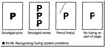
Symptom 3 There are narrow horizontal bands of smudged print. Figure 11-14 shows you an example of this problem. While smudg ing usually suggests a fusing problem, its occurrence in relatively narrow bands actually points to a problem with the paper feed; the registration or transfer rollers are not moving evenly, so they are jerking the paper. When the paper jerks, the toner inunediately be ing transferred from the EP drum becomes smudged.
Check your paper stock first. Unusually light or specially coated papers might slip periodically, resulting in a slight jerking motion. Try a standard 20-lb. xerography-grade paper. If the paper is ap propriate, there are three causes for this kind of paper jerk: either your rollers are worn (allowing loose contact at some point in their rotation); the rollers are obstructed (effectively jamming the pa per at some point in their rotation); or there is a fault in the drive train. Unfortunately, observing the paper path while the printer is running will rarely reveal subtle mechanical defects, so turn off and unplug the printer, then inspect your registration rollers for signs of wear or accumulations of foreign matter. If the registration rollers appear damaged or worn, replace the registration assembly. If there is a buildup of foreign matter, carefully clean the registra tion rollers.
If the problem persists, inspect the drive train carefully. Check each gear to see that they are meshed properly, and see if there are any broken gear teeth. A small, high-intensity pen light will make this inspection easier. Replace any gears that are worn or damaged. If there are obstructions in the gear train, clean them away carefully with a cotton swab lightly dampened in isopropyl alcohol. If this still fails to correct the problem, the fault is proba bly in the EP engine mechanics. Try replacing the EP/toner car tridge (the “engine”).
Symptom 4 There are wide horizontal areas of smudged print. You can see this type of symptom in figure 11-14. Although this prob lem might sound quite similar to the previous symptom, the fault is almost always in the fusing assembly. Excessive pressure from the lower fusing roller squeezes the page so tightly that the print is smudged, typically across a wide area. Turn off and unplug the printer, and allow 15minutes or so for the fusing assembly to cool. Inspect the fusing assembly carefully. If there are torsion springs holding the upper and lower fusing rollers together, you can prob ably reduce the tension to relieve some of the pressure. You might have to work in small increments to get the best results. Also check the lower fusing roller itself; if the roller is worn or dam aged, it should be replaced. As an alternative, you can replace the entire fusing assembly outright.
Symptom 5 There are dark creases in the print. These are visible creases (also referred to as pencil lines) in the page itself, not just in the printed image. In virtually all cases, pencil lines are the result of a bloated lower fusing roller. The way in which it applies pressure on the page causes a crease in the page. First, check your paper supply. Light bond or specially coated papers might be es pecially susceptible to this kind of problem. Try a standard 20-lb. xerography-grade paper. If the problem persists, you will need to inspect the fusing assembly. Turn off and unplug the printer, and allow 15 minutes for the fusing system to cool before opening the printer. Check the lower fusing roller for signs of bloating, exces sive wear, or other damage. Try replacing the lower fusing roller; otherwise, you should replace the entire fusing assembly.
Symptom 6 There is little or no fusing on one side of the image. However, the other half is fused properly. This problem occurs when there is a gap in the fusing rollers. Even if the upper fusing roller is producing the correct amount of heat, it will not fuse toner without pressure from the lower fusing roller. Gaps are often caused from physical damage to the fusing assembly, or an accumulation of foreign matter that forces the rollers apart. Turn off and unplug the printer, then wait about 15 minutes for the fusing assembly to cool. Inspect the rollers carefully. You can expect to fmd your problem on the side that does not fuse. For example, if the right side of the page is not fusing, the problem is likely on the right side of the fusing rollers. Check for mechanical alignment of the rollers. You might be able to restore operation by adjusting tor sion spring tension. If problems continue, you should replace the entire fusing assembly.
Corona (charge roller) problems
There are two high-voltage charge areas inthe EP printer: the pri mary area and the transfer area. Classical “SX-type” engines use corona wires, so the primary area will use a primary corona, and the transfer area will use a transfer corona. The newer “CX-type” engines replace the corona wires with charge rollers, so the pri mary area will use a primary charge roller, and the transfer area will use a transfer charge roller. Although these areas very rarely fail, there are a suite of problems that plague the coronas. This part of the chapter shows you some of the more pervasive faults.
Symptoms
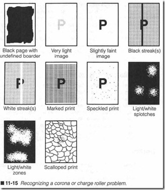
Symptom 1 Pages are completely blacked out, and might appear blotched with an undefined border. You can see an example of this problem in figure 11-15. Turn off and unplug the printer, remove the EP cartridge, and examine its primary corona wire. Remember from Chapter 4 that a primary corona applies an even charge across a drum surface. This charge readily repels toner, except at those points exposed to light by the writing mechanism, which dis charge those points and attract toner. A failure in the primary corona will prevent charge development on the drum. As a result, the entire drum surface will tend to attract toner (even if your writing mechanism works perfectly). This creates a totally black image. If you find a broken or fouled corona wire, clean the wire or replace the EP cartridge.
If your blacked-out page shows print with sharp, clearly defmed borders, your writing mechanism might be running out of control. LEDs in a solid state print bar or laser beam might be shorted inan ON condition, or receiving erroneous data bits from its control cir cuitry (all logic 1s). In this case, the primary corona is working just fme, but a writing mechanism that is always on will effectively ex pose the entire drum and discharge whatever charge was applied
by the primary corona. The net result of attracting toner would be the same, but whatever image is formed would probably appear crisper, more deliberate .
Use yam oscilloscope to measme the data signals reaching yam writing mechanism during a print cycle. You should find a semi random square wave representing the 1s and Os composing the im age. If you fmd only one logic state, troubleshoot your main logic and driving circuits handling the data, or replace the mechanical controller board. If data entering the writing mechanism appears normal, replace your writing mechanism (LED bar or laser/scan ner assembly). You might wish to cross-reference this symptom with an HVPS problem earlier in this chapter.
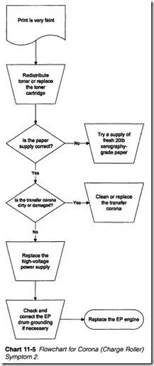
Symptom 2 Print is very faint. Refer to Chart 11-5. Turn off and un plug the printer, remove the EP cartridge, and try redistributing
toner in the cartridge. Your user’s manual probably offers pre ferred instructions for redistributing toner. Keep in mind that toner is largely organic; as such, it has only a limited shelf and use ful life. If redistribution temporarily or partially improves the im age, or if the EP cartridge has been in service for more than six months, replace the EP cartridge. If you are using a paper with a moisture content, finish, or conductivity that is not acceptable, image formation might not take place properly. Try a standard 20- lb. xerography-grade paper.
Check your transfer corona or transfer charge roller. It is the transfer corona that applies a charge to paper that pulls toner off the drum. A weak transfer corona or charge roller might not apply enough charge to attract all the toner in a drum image. This can result in very faint images. Turn off and unplug the printer, allow ample time for the high-voltage power supply to discharge com pletely, then inspect all wiring and connections at the transfer corona. If the monofilament line encircling the transfer corona is damaged, replace the transfer corona assembly, or attempt to re thread the monofilament line. If faint images persist, repair or re place the high-voltage power supply assembly.
Finally, check the drum ground contacts to be sure that they are secure. Dirty or damaged ground contacts will not readily allow exposed drum areas to discharge. As a result, very little toner will be attracted and only faint images will result. If the problem per sists, replace the EP engine.
Symptom 3 Print is just slightly faint. Print that is only slightly faint does not necessarily suggest a serious problem. There are a series of fairly simple checks that can narrow down the problem. Check the print density control dial. Turn the dial to a lower setting to in crease contrast (or whatever darker setting there is for your par ticular printer). Check your paper supply next. Unusual or specially coated paper may cause fused toner images to appear faint. If you are unsure about the paper currently in the printer, insert a good quality, standard-weight xerographic paper and test the printer again.
Over time, natural dust particles in the air will be attracted to the transfer corona and accumulate there. This eventually causes a layer of debris to form on the wire. This type of accumulation cuts down on transfer corona effectiveness, which places less of a charge on paper. Less toner is pulled from the drum, so the result ing image appears fainter. Turn off and unplug the printer, allow ample time for the high-voltage power supply to discharge, then gently clean the transfer corona with a clean cotton swab or corona cleaning tool. Be very careful not to break the monofilament line wrapped about the transfer corona assembly. If this line does break, the transfer corona assembly will have to be rewrapped or replaced.
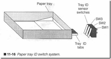
Check your toner level. Unplug the printer, remove the EP car tridge, and redistribute toner. Follow all manufacturer’s recom mendations when it comes to redistributing toner. The toner supply might just be slightly low at the developing roller. Unplug your printer and examine the EP cartridge sensitivity switch settings. These microswitches are actuated by molded tabs attached to your EP cartridge. This tab configuration represents the relative sensitivity of the drum. Main logic uses this code to set the power level of its writing mechanism to ensure optimum print quality. These switches also tell main logic whether an EP cartridge is in stalled at all. If one of these tabs is broken, or if a switch has failed, the drum might not be receiving enough light energy to achieve proper contrast. Check your sensitivity switches as outlined for a “No EP Cartridge” error, shown later in this chapter. If the prob lem persists, your high-voltage power supply is probably failing. Replace your high-voltage power supply.
Symptom 4 There are one or more vertical black streaks in the print. Black streaks might range from narrow lines to wide bands depending on the severity of the problem. In most cases, this fault is due to foreign matter accumulating on the primary corona. For eign matter will prevent charges from forming on the dnun. In turn, this will invariably attract toner, which creates black streaks. Typically, the edges of these streaks are fuzzy and ill-defined. Your best course is simply to clean the primary corona; most printers enclose a cleaning tool for just this purpose. The process takes no more than a minute. If the problem should persist (very unlikely), replace the EP engine.
Symptom 5 There are one or more vertical white streaks in the print. Begin by checking your toner level. Toner might be distrib uted unevenly along the cartridge’s length. Turn off and unplug the printer, remove the EP cartridge, and redistribute the toner. Follow your manufacturer’s recommendations when handling the EP cartridge. If this improves your print quality (at least tem porarily), replace the nearly exhausted EP cartridge.
Next, examine your transfer corona for areas of blockage or ex treme contamination. Such faults would prevent the transfer corona from generating an even charge along its length; corrosion acts as an insulator that reduces the corona’s electric field. Un charged page areas will not attract toner from the drum, so those page areas will remain white. Clean the transfer corona very care fully with a clean cotton swab. If your printer comes with a corona cleaning tool, use that instead. When cleaning, be sure to avoid the monofilament line wrapped around the transfer corona assembly. If the line breaks, it will have to be rewrapped, or the entire trans fer corona assembly will have to be replaced.
Check the optical assembly for any accumulation of dust or debris that could block out sections of light. Because EP drums are only scanned as fine horizontal lines, it would take little more than a fragment of debris to block light through a focusing lens. Gently blow off any dust or debris with a can of high-quality, optical-grade compressed air available from any photography store. For stains or stubborn debris, clean the afflicted lens gently with a high-qual ity lens cleaner and wipes from any photography store. Be very careful not to dislodge the lens from its mounting. Never blow on a lens or mirror yourself; breath vapor and particles can condense and dry on a lens to cause even more problems in the future.
Symptom 6 The print appears “scalloped.” You can see an example of “scalloping” in figure 11-15. The scalloping effect has a unique and unmistakable appearance, and almost always indicates that the primary corona has broken. The image that forms is then ex pressly the result of random discharge from the erase lamps. In many cases, the failure of a primary corona will simply blacken the page. In some circumstances, however, the erase lamps will leave a latent image that will develop into the scalloped pattern. You should immediately suspect a failure in the primary corona. Your best course is simply to replace the primary corona by exchanging the EP/toner cartridge.
Symptom 7 The print suggests a shorted transfer corona, as shown in figure 11-15. An image appears as expected, but it is marked with vertical swatches of small horizontal tics. Experience has demonstrated that this type of symptom is frequently due to a short-circuited transfer corona. Turn off and unplug the printer, then allow at least 15 minutes for the printer to cool and dis charge. Inspect the transfer corona carefully, as well as any wiring at the corona. Gently clear away any foreign material, especially conductive material, from the transfer area, and try the printer again. If the problem persists, try replacing the transfer corona as sembly.
Symptom 8 Print appears speckled. In almost all cases, speckled print is the result of a fault in your primary corona grid. A grid is essentially a fme wire mesh between the primary corona and drum surface. A constant voltage applied across the grid serves to regu late the charge applied to the drum to establish a more consistent charge distribution. Grid failure will allow much higher charge lev els to be applied unevenly. A higher conditioning charge might not be discharged sufficiently by the writing mechanism; toner might not be attracted to the drum even though the writing is working as expected. This results in a very light image (almost absent except for some light speckles across the page). Because the primary grid assembly is part of the EP cartridge, replace the EP/toner car tridge and retest the printer. If speckled print persists, you should suspect a fault in the HVPS.
Symptom 9 There are light/white splotches inthe image. When you see a symptom such as this, your first suspicion should be mois ture in the paper supply, which is a common occurrence in humid sununer months. When the paper becomes damp (even just from the air’s humidity), charges do not distribute properly across the page. As a result, paper will not charge in the damp areas, so toner is not attracted from the drum. Damp areas then remain very light or white. Paper that is unusually coated can have similar problems. In virtually all cases, a supply of fresh, dry, 20-lb., xerography-grade paper should correct the problem. To correct the problem over the long term, consider adding a dehumidifier or air
conditioner in the work area to keep paper dry.
Symptom 10 There are light/white zones spread through the im age. At first glance, you might think that this symptom is similar to the previous one. In practice, however, random white zones in the printed page are much larger and more distinct than simple light splotches; in effect, the white areas have just disappeared. This symptom is indigenous to the CX-type EP engine that uses charge rollers rather than coronas. In most cases, you will find that the transfer charge roller has failed or is missing. Even without a working transfer corona, the CX engine can transfer portions of the latent image to the page, but you can see from figure 11-15 that the transfer is very unstable. Check and replace the transfer charge roller or replace the EP engine outright.
Miscellaneous problems
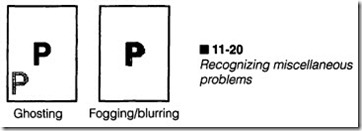
This chapter has focused on problems that plague key areas of the EP printer. However, there are some symptoms that cannot easily be associated with any particular area of the printer. As a conse quence, these problems can be difficult to track down and correct. This part of the chapter illustrates some of the printer’s miscella neous problems.
Symptoms
Symptom 1 Your printer never leaves its warm-up mode. There is a continuous “Warming Up” status code. EP printers must perform two important tasks during initialization. First, a self-test is per formed to check the printer’s logic circuits and electromechanical components. This usually takes no more than 10 seconds from the time power is first applied. Second, its fusing rollers must warm up to a working temperature. Fusing temperature is typically accept able within 90 seconds from a cold start. At that point, the printer will establish communication with the host computer and stand by to accept data, so its “Warming Up” code should change to an “On Line” or “Ready” code.
When the printer fails to go on-line, it might be the result of a faulty communication interface, or a control panel problem. ‘fum the printer off, disconnect its communication cable, and restore power. If the printer finally becomes ready without its conununication cable, check the cable itself and its connection at the computer. You might have plugged a parallel printer into the computer’s serial port, or vice versa. There might be a faulty com munication interface in your host computer.
If the printer still fails to become ready, unplug the printer and check that the control panel cables or interconnecting wiring is at tached properly. Check the control panel to see that it is operating correctly. Also check the control panel interface circuit (some times called an interface/formatter circuit). Repair or replace your faulty control panel or interface/formatter circuit. Depending on the complexity of your particular printer, the interface/format ter might be a separate printed circuit plugged into the main logic board, or its functions might be incorporated right into the main logic board itself.
Symptom 2 You fmd a “Paper out” message. When the printer gen erates a “Paper out” message, it means that either paper is ex hausted, or the paper tray has been removed. When a paper tray is inserted, a series of metal or plastic tabs make contact with a set of microswitches, as shown in figure 11-16. The presence or ab sence of tabs will form a code that is unique to that particular paper size. Microswitches are activated by the presence of tabs. Main logic interprets this paper type code, and knows automatically what kind of media (paper, envelopes, etc.) that it is working with. This allows the printer to automatically scale the image according to paper size. Table 11-1shows a typical paper code table.
The presence of paper is detected by a mechanical sensing lever, as shown in figure 11-17. When paper is available, a lever rests on the paper. A metal or plastic shaft links this lever to a thin plastic flag. While paper is available, this flag is clear of the paper-out sen sor. If the tray becomes empty, this lever falls through a slot in the tray, which rotates its flag into the paper-out sensor. This indicates that paper is exhausted. The paper-out sensor is usually mounted on an auxiliary PC board (known as the paper control board), and its signal is typically interpreted by the mechanical controller board.
Begin your check by removing the paper tray. Be sure that there is paper in the tray, and that any ID tabs are intact, especially if you have just recently dropped the tray. Reinsert the filled paper tray carefully and completely. If the “Paper out” message continues, then there is either a problem vvith your paper ID rnicroswitches , paper-sensing lever, or the paper-out optoisolator.
You can check the paper ID rnicroswitches by removing the paper tray and actuating the paper sensing lever by hand (so the printer thinks that paper is available). Refer to Table 11-1 and actuate each switch in turn using the eraser of a pencil. Actuate one switch at a time and observe the printer’s display. The “Paper out” error should go away whenever at least one rnicroswitch is pressed. If the error remains when a switch is pressed, that switch is probably defective. Unplug the printer and use your multi.m eter to check continuity across the suspect switch as you actuate it. Replace any defective switch. If the switches work electrically, but the printer does not register them, troubleshoot or replace the main logic board. Inspect the paper-out lever and optoisolator next.
When paper is available, the paper-out lever should move its plas tic flag clear of the optoisolator. When paper is empty, the lever should place its flag into the optoisolator slot. Note: This logic might be reversed depending on the particular logic of the printer. This check confirms that the paper sensing arm works properly. If you see the lever mechanism jammed or bent, repair or replace the mechanism. Check the paper-out optoisolator, as shown in the procedures of Chapter 9. Replace the optoisolator if it appears de fective. If the sensors appear operational, replace the mechanical controller board.
Symptom 3 You see a “Printer open” message. Printers can be opened in order to perform routine cleaning and EP cartridge re placement. The cover(s) that can be opened to access your printer are usually interlocked with the writing mechanism and high-volt age power supply to prevent possible injury from laser light or high voltages while the printer is opened. A simplified interlock assembly is shown in figure 11-18. The top cover (or some other cover assembly) uses a pushrod to actuate a simple electrical switch. When the top cover is opened, the interlock switch opens, and the printer’s driver voltage (+24 Vde is shown) is cut off from all other circuits. This effectively disables the printer’s operation.
When the top cover is closed again, the interlock switch is reactivated, and printer operation is restored.
Make sure that your cover(s) are all shut securely (try open ing and reclosing each cover). Inspect any actuating levers or pushrods carefully. Replace any bent, broken, or missing me chanical levers. Unplug the printer and observe how each in terlock is actuated (it might be necessary to disassemble other covers to observe interlock operation). Adjust the pushrods or switch positions if necessary to ensure firm contact.
Turn off and unplug the printer, then use your multimeter to mea sure continuity across any questionable interlock switches. It might be necessary to remove at least one wire from the switch to prevent false readings. Actuate the switch by hand to be sure that it works properly. Replace any defective interlock switch, reattach all connectors and interconnecting wiring, and retest the printer. If the switch itself works correctly, check the signals feeding the switch. For figure 11-18, check the de voltage at the switch. If the voltage is low or absent, trace the voltage back to the power sup ply or other signal source. If signals are behaving as expected but a “Printer open” message remains, trace the interlock signal into the mechanical controller board and troubleshoot your electron ics, or replace the mechanical controller outright.
Symptom 4 You see a “No EP cartridge” message. An elec trophotographic engine assembly uses several tabs (known as sensitivity tabs) to register its presence, as well as inform the printer about the drum’s relative sensitivity level. The ECU regulates the output power of its writing mechanism based on these tab arrangements (e.g., high-power, medium-power, low power, or no-power, no cartridge). Sensitivity tabs are used to actuate microswitches located on a secondary PC board. The sequence of switch contacts forms a “sensitivity” code that is interpreted by the mechanical controller.
Begin by checking the installation of your current EP engine. Make sure that it is in place and seated properly. Check to be sure that at least one sensitivity tab is actuating a sensor switch. If there are no tabs on the EP engine, replace it with a new or cor rect-model EP engine having at least one tab. Retest the printer. If your “No EP cartridge” error persists, check all sensitivity switches in the printer. Turn off and unplug the printer, then use your mul timeter to measure continuity across each sensitivity switch. It might be necessary to remove at least one wire from each switch to prevent false continuity readings. Actuate each switch by hand and see that each one works properly. Replace any microswitch that appears defective or intermittent. Replace any connectors or interconnecting wiring, and retest the printer. If the sensitivity switches are working properly , troubleshoot or replace the me chanical controller board or replace it outright.
Symptom 5 You see a “Toner low” message constantly, or the error never appears. A toner sensor is located within the EP/toner car tridge itself. Functionally, the sensor is little more than an antenna receiving a signal from the high-voltage ac developer bias, as shown in figure 11-19. When toner is plentiful , much of the elec tromagnetic field generated by the presence of high-voltage ac is blocked. As a result, the toner sensor only generates a small volt age. This weak signal is often conditioned in the mechanical con troller by an amplifier using some type of operational amplifier circuit that compares sensed voltage to a preset reference voltage. For the sensor in figure 11-19, sensed voltage is normally below the reference voltage; its output is a logic 0. Main logic would in terpret this signal as a satisfactory toner supply. As toner volume decreases, more high-voltage energy is picked up by the toner sensor, in tum developing a higher voltage signal. When toner is too low, sensed voltage will exceed the reference, and the com parator’s output will switch to a logic 1. This is handled in main logic, and a “Toner low” warning is produced.
Unfortunately, there is no good way to test the toner sensor. High voltage is very dangerous to measure directly without the appro priate test probes, and the signal picked up at the receiving wire is too small to measure without a sensitive meter or oscilloscope. Turn off and unplug the printer and begin your check by shaking the toner to redistribute the toner supply (or insert a fresh EP/toner cartridge). Refer to the user’s manual for your particular printer to fmd the recommended procedure for redistributing toner, then retest the printer. If the problem persists, there might be a fault in the mechanical controller board’s detection circuit. Troubleshoot the mechanical controller or replace it entirely.
Symptom 6 Your printer’s LCD displays a “fan motor error” or sim ilar fault. The printer might also use an error code (e.g., ERROR 34) to represent the condition. The typical EP printer uses two fans: a high-voltage cooling fan, and an ozone venting fan. In most cases, the ozone venting fan runs off-line and is not detected by the printer. The power supply cooling fan, however, is vital for the supply’s reliability; if the cooling fan fails, the power supply will quickly overheat and fail. To prevent this from happening, the fan’s operation is often monitored. If the fan quits, an error will be pro duced. In most cases, the fan is simply defective and should be re placed. Check the voltage available at the fan. If fan voltage is available (but the fan does not spin), the fan is defective and should be replaced. If fan voltage is missing, you will need to work back into the printer to fmd where fan power was lost; check any loose wiring or connectors.
Symptom 7 There is ghosting in the image. The expected image prints normally, but upon inspection, you can see faint traces of previous image portions, as shown in figure 11-20. This is a case of poor housekeeping; ordinarily, a cleaning blade should scrape away any residual toner remaining on the EP drum prior to eras ing and conditioning. If the cleaning blade is worn out, or the scrap toner reservoir is full, cleaning might not take place as expected, and toner will remain on the EP drum for one or more subsequent rotations. If the residual toner comes off on another rotation, it will often appear as the “ghost” of a previous image. Unfortunately, the only way to really correct this problem is to replace the entire EP engine. Cleaning blades are hardly replaceable parts, and if the scrap toner bin is full, there is no way to recycle the toner back into the reservoir. Turn off and unplug the printer, replace the EP engine, and try the printer again.
Symptom 8 The print appears fogged or blurred. This might appear somewhat like smudging inprevious symptoms, but where smudg ing was generally limited in other symptoms, it occurs throughout the page here. This is a situation where you should examine the paper transfer guide, the passage between the static discharge comb (the transfer area) and the fusing assembly. Most transfer guides are coated with Teflon or similar material to reduce static. Over time and use, the antistatic coating can wear off revealing the static-prone plastic below the coating. If the plastic of the transfer guide causes a static charge, it might be strong enough to “drag” the toner image just slightly, resulting in a blurred of fogged image. If you find wear in the transfer guide, replace the transfer guide assembly.
