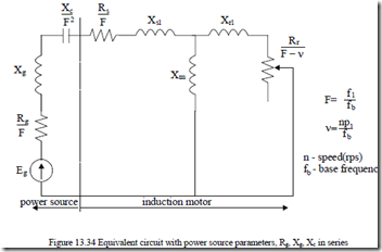
Subsynchronous series resonance may occur when the induction motors are fed from a power source that shows a series capacitance (Figure 13.34). It may lead to severe oscillations in speed, torque, and current. It appears, in general, during machine starting or after a power supply fault.
fb is the base frequency, f1 is the current frequency, n is the rotor speed. The reactances are written at base frequency.
It is self evident that the space phasor model may be used directly to solve this problem completely, provided a new variable (capacitor voltage Vc) is introduced.
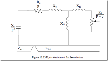
The total solution contains a forced solution and a free solution. The complete mathematical model is complex when magnetic saturation is considered. It simplifies greatly if the magnetization reactance Xm is considered constant (though at a saturated value). In contrast to the induction capacitorexcited generator, the free solution here produces conditions that lead to machine heavy saturation.
In such conditions we may treat separately the resonance conditions for the free solution.
To do so we lump the power source impedance Rg, Xg into stator parameters to get Re = Rs + R ; Xg e = Xg + Xsl (13.138) and eliminate the generator (power source) emf Eg (Figure 13.35).
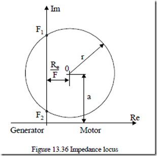
To simplify the analysis, let us use a graphical solution. The internal impedance locus is, as known, a circle with the center 0 at 0 Re ,a . [28]
F
a ≈ Xe + 2(XXe +e2Xm ) (13.139)
and the radius r
r ≈ 2(XXe +e2Xm ) (13.140)
On the other hand, the external (the capacitor, in fact) impedance is represented by the imaginary axis (Figure 13.36). The intersection of the circle with the imaginary axis, for a given capacitor, takes place in two points F1 and F2 which correspond to reference conditions. F1 corresponds to the lower slip and is the usual self excitation point of induction generators.
The p.u. values of frequencies F1 and F2, for a given series capacitor Xc and resistor, Re, reactance Xe, are
F1 ≈ Xe + Xm
Xc
![clip_image001[4] clip_image001[4]](http://machineryequipmentonline.com/electric-equipment/wp-content/uploads/2017/04/clip_image0014_thumb10.gif) F2 ≈ Xe + XXX Xmcm+ Xrl rl (13.141)
F2 ≈ Xe + XXX Xmcm+ Xrl rl (13.141)
Alternatively, for a given resonance frequency and capacitor, we may obtain the resistance Re to cause subsynchronous resonance. With F = F1 given, we may use the impedance locus to obtain Re.
![]() XF 2c = a + r2 − RF1e 2 (13.142)
XF 2c = a + r2 − RF1e 2 (13.142)
1
Also, from the internal impedance at Re(Zint) = 0 equal to Xc/F12, the value of speed (slip: F–ν) may be obtained.
Xc
slip = F −ν ≈ ± Rr Xm −Xe − F12 (13.143)
 1 (Xm + Xrl ) XF1c −Xe (Xm + Xrl )−X Xm rl
2
In general, we may use Equation (13.143) with both ± to calculate the frequencies for which resonance occurs.
F a4 ( 2 − +r2 ) F R2 ( e2 −2aXc )+Xc2 = 0 (13.144)
The maximum value of Re, which still produces resonance, is obtained when the discriminant of (13.144) becomes zero.
The corresponding frequency,
F R( (13.146)
This way the range of possible source impedance that may produce subsynchronous resonance (SSR) has been defined.
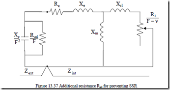
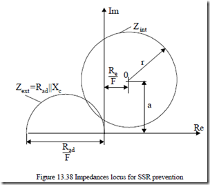
Preventing SSR may be done either by increasing Re above Remax (which means notable losses) or by connecting a resistor Rad in parallel with the capacitor (Figure 13.37), which means less losses.
A graphical solution is at hand as Zint locus is already known (the circle). The impedance locus of the Rad||Xc circuit is a half circle with the diameter Rad/F and the center along the horizontal negative axis (Figure 13.38).
The SSR is eliminated if the two circles, at same frequency, do not intersect each other. Analytically, it is possible to solve the equation:
Zext + Zint = 0 (13.146’) again, with Rad||Xc as Zext.
A 6th order polynomial equation is obtained. The situation with a double real root and 4 complex roots corresponds to the two circles being tangent. Only one SSR frequency occurs. This case defines the critical value of Rad for SSR. In general, Rad (critical) increases with Xc and so does the corresponding SSR frequency. [27, 28]
Using a series capacitor for starting medium power IMs to reduce temporary supply voltage sags and starting time is a typical situation when the prevention SSR is necessary.
