IGBT SWITCHING TRANSIENTS
Voltage transients are generated due to the switching in the PWM inverter. They prop- agate down the power cables to the motor. If the motor cables are not terminated prop- erly, the switching waves will be reflected when they reach the motor. They will be transiently increased or decreased depending on the relative impedance between the line and the load. An alternative solution for this problem would be to slow down the rate of voltage rise.
If the connecting cable is long, the mismatch of impedances will generate a voltage reflection at the point where the line impedance changes (at the motor terminals). A transient rise in voltage of the wave will occur at the motor terminals due to the voltage reflection.
For a given switching rise time, the voltage rise at the terminals will increase with the length of the connecting cable. The wave front is reflected back to the inverter. If no mit- igating actions are taken, the transient voltage at the motor terminals can double that of the inverter in the worst case. In most cases, the reflection problem increases gradually with the length of the motor cable. The rise in transient voltage is important for the following reasons.
Insulation Voltage Stress
The increase in voltage stress in the motor connecting cables and the motor insulation will shorten the lifetime of the insulation. If the peaks of any of the voltage transients exceed the insulation corona discharge level (partial discharge level), the insulation will degrade with each voltage pulse. It will eventually fail.
The new “inverter-rated” motors have triple-layer insulation. They have a 1600- to 2000-V partial discharge level. This allows them to withstand double the voltage peak transient from a 600-V inverter. Since most “standard” induction motors can withstand about 1200 V, its use in this application will shorten its life drastically. It can be as low as a few hours only.
Motor Winding Voltage Distribution
All high-frequency transient voltages tend to be unevenly distributed across the motor windings. The high frequencies develop greater voltages across the first windings rather than being evenly distributed across the whole length of the windings. The effect of high- frequency transients tends to be accentuated on the first few windings. This is where most motor insulation failures occur. The problem becomes worse when the frequency of the transients (i.e., the IGBT switching speed) is higher.
This problem does not occur with drives using older transistors or GTOs because the switching speeds are much lower (2 to 4 j.Ls). When the drive uses IGBTs with switching speeds of 50 to 150 ns, the motor should be connected to the inverter by a cable shorter than 20 ft, or special precautions should be taken.
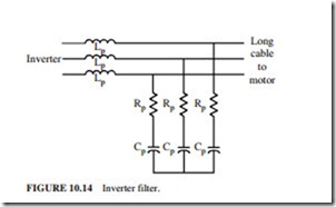
This problem can be solved by adding a filter to the output of the inverter to slow down the IGBT switching transients (Fig. 10.14). When the inverter switching speed is reduced, the length of the connecting motor cable can be increased.
Radiated Electromagnetic Interference (EMI)
The bandwidth (hertz) of any radiated EMI increases inversely proportionally to the rise time of the voltage transients. Since the IGBTs have a switching speed of 50 ns, EMI frequencies in the megahertz range are generated. These frequencies radiate very well.
This radiation is not limited to the motor cables only. They will also occur (to a lower level) on the ac source input to the inverter due to common-mode voltage problems. The radiation problem can be solved by installing a power line EMI filter.
The inverter switching problems can be solved by any of the following three solutions:
Cable Terminating (Matching) Impedance
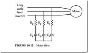
An RC (resistance-capacitance) filter can be added to the motor terminals. Its impedance should match that of the connecting cable (Fig. 10.15). The reflected voltage will be can- celed by removing the discontinuity of the impedance. This will reduce the motor and cable insulation stress. This solution has three disadvantages:
● Cost is high.
● It dissipates power.
● The filter must be added in a very inhospitable environment at the motor termination box. This solution prevents voltage reflection. Therefore, it reduces insulation stress. However, it does not change the switching speed of the inverter. Thus, the high voltage rise (dυ/dt) will still be impressed on the motor insulation.
Inverter Output Filter
When a filter is added, like the one shown in Fig. 10.14, at the output of the inverter, the rise time of the voltage transients will be reduced to that of the GTOs due to the series inductors. The voltage reflection problems will be reduced significantly due to the decrease in voltage rise time. This will allow longer cables to the motor. The RC part of the filter is needed to dampen the switching transients. This filter is also costly, dissipates power, and requires large space in the inverter.
The most effective type of this filter is a large one that prevents switching voltages from propagating. In this case, there will not be any switching, insulation, or EMI problems. This type would be ideal for a drive used with an existing older motor having a suspect insulation. Since the filter’s inductances have reduced the voltage rise times to the motor, the radiated EMI and the motor bearing currents are also reduced. This is the best overall solution (even with the increase in cost). In general, this is a standard part of the inverter, or it is available as an option in most commercial inverters.
Extra Insulation
This approach involves adding extra insulation to the magnet wire in the motor and con- necting cable to handle the additional voltage caused by switching. A typical insulation for inverter duty motors has three layers. It can withstand the voltage transients of a 600-V inverter without corona discharge (standard motors cannot be used for these applications).
The cable insulation problem must also be addressed. A 2000-V cable should be used (depending on the length of the connecting cable) for a 600-V IGBT inverter. This solution does not reduce the waveform rise time. Therefore, it does not address the motor bearing current or EMI radiation problems.

