Overload Size
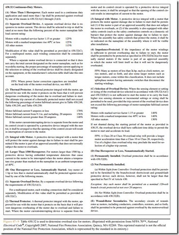
When determining the overload size for a motor, the nameplate current rating of the motor is used instead of the current values listed in the tables (NEC Section 430.6(A)(1)). Other factors such as the service factor (SF) or temperature rise (°C) of the motor are also to be considered when determining the overload size for a motor. The temperature rise of the motor is an indication of the amount of temperature increase the motor should experience under a full load conditon and should not be confused with termination temperature discussed in Section 110.14(C). NEC Section 430.32 (Figure 47 – 9) is used to determine the overload size for motors of 1 horsepower or more. The overload size
EXAMPLE:
is based on a percentage of the full load current of the motor listed on the motor nameplate.
If for some reason this overload size does not per- mit the motor to start without tripping out, Section 430.32(C) permits the overload size to be increased to a maximum of 140% for this motor. If this increase in overload size does not solve the starting problem, the overload may be shunted out of the circuit during the starting period in accordance with Section 430.35(A)&(B).
Determining Locked Rotor Current
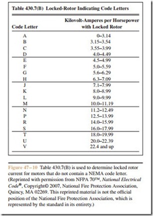
There are two basic methods for determining the locked rotor current (starting current) of a squirrel cage induction motor, depending on the information avail- able. If the motor nameplate lists code letters that range from A to V, they indicate the type of rotor bars used when the rotor was made. Different types of bars are used to make motors with different operating charac- teristics. The type of rotor bars largely determines the maximum starting current of the motor. NEC Table 430.7(B) (Figure 47 – 10) lists the different code letters and gives the locked-rotor kilovolt-amperes per horse- power. The starting current can be determined by mul- tiplying the kilovolt-ampere rating by the horsepower rating and then dividing by the applied voltage.
EXAMPLE:
A 15 horsepower, three-phase squirrel cage motor with a code letter of K is connected to a 240 volt line. Determine the locked-rotor current.
The table lists 8.0 to 8.99 kilovolt-amperes per horsepower for a motor with a code letter of K. An average value of 8.5 will be used.
8.5 X 15 = 127.5 kVA or 127,500 VA
127,500
A 25 horsepower three-phase induction motor has a nameplate rating of 32 amperes. The nameplate also shows a temperature rise of 30°C. Determine
240 X V3
= 306.7 amperes
the ampere rating of the overload for this motor.
NEC Section 430.32(A)(1) indicates the over- load size is 125% of the full load current rating of the motor.
32 X 1.25 = 40 amperes
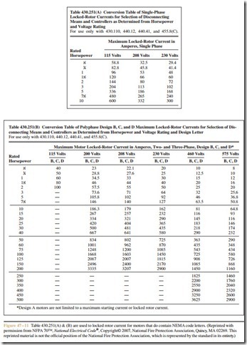
The second method of determining locked rotor current is to use Tables 430.251(A)&(B) (Figure 47 – 11) if the motor nameplate lists NEMA design codes. Table 430.251(A) lists the locked rotor currents for single- phase motors and Table 430.251(B) lists the locked ro- tor currents for poly-phase motors.
Short-Circuit Protection
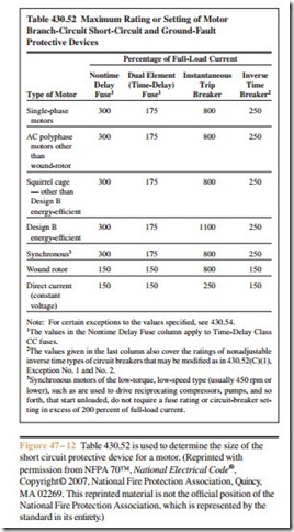
The rating of the short-circuit protective device is determined by NEC Table 430.52 (Figure 47 – 12). The far left-hand column lists the type of motor that is to be protected. To the right of this are four columns that list different types of short-circuit protective devices; non-time delay fuses, dual-element time delay fuses, instantaneous trip circuit breakers and inverse time circuit breakers. Although it is permissible to use non- time delay fuses and instantaneous trip circuit breakers, most motor circuits are protected by dual-element time delay fuses or inverse time circuit breakers.
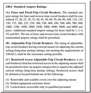
Each of these columns lists the percentage of motor current that is to be used in determining the ampere rating of the short-circuit protective device. The current listed in the appropriate motor table is to be used instead of the nameplate current. NEC Section 430.52(C)(1) states that the protective device is to have a rating or setting not exceeding the value calculated in accord with Table 430.52. Exception No. 1 of this section, however, states that if the calculated value does not correspond to a standard size or rating of a fuse or circuit breaker, it shall be permissible to use the next higher standard size. The standard sizes of fuses and circuit breakers are listed in NEC Section 240.6 (Figure 47 – 13).
Starting in 1996, Table 430.52 has listed squirrel cage motor types by NEMA design letters instead of code letters. Section 430.7(A)(9) requires that motor nameplates be marked with design letters B, C, or D. Motors manufactured before this requirement, how- ever, do not list design letters on the nameplate. Most common squirrel cage motors used in industry actually fall in the design B classification and for purposes of selecting the short-circuit protective device are considered to be design B unless otherwise listed.
EXAMPLE:
A 100 horsepower three-phase squirrel cage induction motor is connected to a 240 volt line. The motor does not contain a NEMA design code. A dual-element time delay fuse is to be used as the short-circuit protective device. Determine the size needed.
Table 340.250 lists a full load current of
248 amperes for this motor. Table 430.52 indicates that a dual-element time delay fuse is to be calculated at 175% of the full load current rating for
an AC polyphase (more than one phase) squirrel cage motor, other than design code E. Since the motor does not list a NEMA design code on the nameplate, it will be assumed that the motor is design B.
248 X 1.75 = 434 amperes
The nearest standard fuse size above the computed value listed in Section 240.6 is 450 amperes, so
450 ampere fuses will be used to protect this motor.
If for some reason this fuse will not permit the mo- tor to start without blowing, NEC Section 430.52(C)(1) Exception 2(b) states that the rating of a dual-element time delay fuse may be increased to a maximum of 225% of the full load motor current.
Starter Size
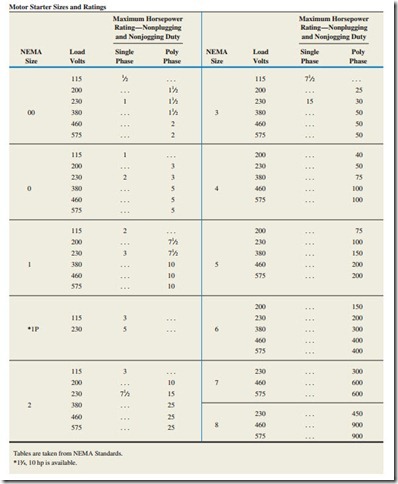
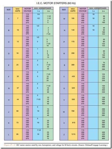
Another factor that must be considered when in- stalling a motor is the size of starter used to connect the motor to the line. Starter sizes are rated by motor type, horsepower, and connected voltage. The two most common ratings are NEMA and IEC. A chart showing common NEMA size starters for alternating current motors is shown in Figure 47 – 14. A chart showing IEC starters for alternating current motors is shown in Figure 47 – 15. Each of these charts lists the minimum size starter designed to connect the listed motors to the
line. It is not uncommon to employ larger size starters than those listed. This is especially true when using IEC type starters because of their smaller load contact size.
EXAMPLE:
A 40 horsepower three-phase squirrel cage motor is connected to a 208 volt line. What are the mini- mum size NEMA and IEC starters that should be used to connect this motor to the line?
NEMA: The 200 volt listing is used for motors rated at 208 volts. Locate the NEMA size starter that corresponds to 200 volts and 40 horsepower. Since the motor is three-phase, 40 horsepower will be in the polyphase column. A NEMA size 4 starter is the minimum size for this motor.
IEC: As with the NEMA chart, the IEC chart lists 200 volts instead of 208 volts. A size N starter lists 200 volts and 40 horsepower in the three-phase column.
Related posts:
Incoming search terms:
- In general what is the maximum overload rating for a 10 HP 240 volt three-phase squirrel cage motor?
- overload size
- determining overload rating
- nema overload size chart
- motor overloads sizes lists
- 100-hp three-phase squirrel-cage induction motor is connected to a 240-volt line The motor contain a NEMA design code B
- A 15-hp three-phase squirrel-cage motor with a code letter of H is connected to a 240-volt line Determine the locker-rotor current using Table 430 7(B) (use the higher value of the range)
- A 100-horsepower three-phase squirrel-cage induction motor is connected to a 240-volt line A dual-element time-delay fuse is to be used as the short-circuit protective device What is the correct fuse rating?
- 430*52
- shop7is
