PERFORMANCE OBJECTIVES
After studying this chapter, you will be able to:
1. Describe how a split-phase motor can be reversed.
2. List uses for the split-phase motor.
3. Identify the repulsion-induction motor.
4. Identify the capacitor-start motor.
5. Explain how to reverse the direction of rotation of a capacitor-start motor.
6. Describe the best use for the permanent splitcapacitor motor.
7. Explain how a shaded-pole motor operates.
8. List various motor starter methods.
9. Explain how primary resistor starting operates.
10. Explain how part-winding starting is accomplished.
11. List the advantages and disadvantages of partwinding starters.
12. Describe how wye-delta and star-delta starters work.
13. List the advantages and disadvantages of wyedelta and star-delta starters.
14. Describe the operation of consequent-pole motor controllers.
15. Identify the least expensive type of starter.
16. List basic characteristics of five types of starting methods.
17. Select a starter for a desired characteristic.
ELECTRIC MOTORS
Electric motors are designed to deliver their best overall performance when operated at the design voltage shown on the nameplate. However, this voltage is often not maintained. Instead, it varies between minimum and maximum limits over what is termed voltage spread. The voltage spread is usually due to the wiring and transformers of the electrical distribution system and varies in proportion to motor or load currents
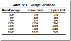
In most modern plants using load center power distribution systems, variations in voltage normally will be within recommended limits of 110 to 120, 220 to 240, 440 to 480, and 550 to 600 for single phase and threephase squirrel cage and synchronous motors. However, there are older plants throughout the country with large low voltage systems. Long low voltage feeders often cause voltage drops that result in below standard voltages at the motor terminals, especially during motor starting, when currents may be up to six times normal full load. Table 12 1 shows the effect of voltage variations on the performance of polyphase induction motors
Single phase and polyphase motors call for different approaches or methods to start them under various conditions of operation. Most single phase motors are started by the turning on of an on off switch or a magnetic starter
STARTING THE MOTOR
One of the most important parts of the electric motor is the start mechanism. A special type is needed for use with single phase motors. A centrifugal switch is used to take a start winding out of the circuit once the motor has come up to within 75% of its run speed. The split phase, capacitor start, and other variations of these types all need the start mechanism to get them running.
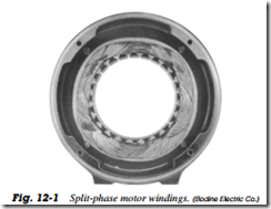
The stator of a split phase motor has two types of coils, one called the run winding and other the start winding. The run winding is made by winding the enamel coated copper wire through the slots in the stator punchings. The start winding is made in the same way except that the wire is smaller. Coils that form the start windings are positioned in pairs in the stator directly opposite each other and between the run windings. When you look at the end of the stator, you see alternating run windings and start windings (Fig. 12 1).
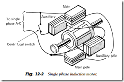
The run windings are all connected together, so the electrical current must pass through one coil completely before it enters the next coil, and so on through all the run windings in the stator. The start windings are connected together in the same way and the current must pass through each in turn (Fig. 12 2)
The two wires from the run windings in the stator are connected to terminals on an insulated terminal block in one end bell where the power cord is attached to the same terminals. One wire from the start winding is also tied to one of these terminals. However, the other wire from the start winding is connected to the stationary switch mounted in the end bell. Another wire then connects this switch to the opposite terminal on the insulated block. The stationary switch does not revolve but is placed so that the weights in the rotating portion of the switch, located on the rotor shaft, will move outward when the motor is up to speed and open the switch to stop electrical current from passing through the start winding
The motor then runs only on the main winding until such times as it is shut off. Then, as the rotor decreases in speed, the weights on the rotating switch again move inward to close the stationary switch and engage the start winding for the next time it is started
Reversibility
The direction of rotation of the split phase motor can be changed by reversing the start winding leads
Uses
This type of motor is used for fans, furnace blowers, oil burners, office appliances, and unit heaters


