REMOTE CONTROLS
One convenient feature of modern TV receivers is their remote control operation. Remote control, as the name implies, is a system by which one is able to control the performance of an equipment placed at a distance.
Many television receivers have provisions for operating the ON-OFF, volume, main tuning, picture contrast and brightness adjustments remotely from a normal viewing distance. The command signal travels to the set in a variety of ways depending on the system. By far, the most popular remote control systems are those which employ ultrasonic signals. The frequencies commonly used for remote control lie in the 40 kHz range.
The remote system has three main components—a remote transmitter, a remote receiver and the devices at the receiver to effect the change ordered by the remote command. These include motors, relays and, in the latest systems, electronic control devices.
ULTRASONIC TRANSDUCERS
The operation of an acoustic type remote control system depends upon the use of transducers. One transducer in the transmitter, i.e. in the hand-held remote control unit, converts a mechanical vibration into high-frequency sounds. Another transducer in the receiver converts the high-frequency sounds into electrical signals which can be used for operating a control in the receiver.
Two basic transmitter types are used. The first is the mechanical or “bonger type” which employs a cylindrical aluminium rod which vibrates in its longitudinal mode when struck. If such a rod is struck on one end by a hammer moving along its axis, it emits a sustained note which has a definite frequency. For example, an aluminium rod 2½” long has a fundamental resonant frequency of about 40 kHz. The internal damping of the aluminium rod is so slight that a large part of the vibrational energies stored in the rod, after the original blow of the hammer, is radiated.
A single rod of a specified length will produce a certain resonant frequency. Thus, to control three or four functions within a television receiver, three or four rods of slightly different lengths have to be used. In a typical transmitter, the working parts include a hammer and a steel cylinder weighing about 2½ grams located at one end of the cylindrical rod. When a button is pressed, the hammer is pushed away from the rod by the force of a spring. As the button is pressed further, the spring is suddenly released and the hammer strikes the rod. Usually, if more than one hammer is employed, the difference in frequencies of the various rods may be to the tune of 1000 Hz or more.
Once the rod is struck and the energy transmitted, it is essential to dampen the remaining energy as quickly as possible. For this purpose, a mechanical damping method is employed. In this method, damping is achieved by a small piece of spring wire, covered by a plastic sleeve, which protrudes through the mounting and touches the rod. When the button is pressed, the damper is withdrawn and when it is released, the sleeve again makes contact with the rod.
In the receiver, the ultrasonic energy is picked up by a crystal type microphone using a barium titanate crystal element. This material, when cut in the form of a small bar or plate, is mechanically strained by the sound waves. Conversely, when a voltage is applied across the two electrodes, the barium titanate gets mechanically strained. This is the well known piezoelectric effect.
In Fig. 35.1 (a) two thin rectangular wafers of barium titanate are combined together. The conducting electrode silver, is applied at both the ends of the wafers. These electrodes are shown by the dark portion on both ends of the assembly. Between the two wafers, at the nodal points of vibration, two thin metal strips are cemented which serve as electrical contacts and as a mechanical suspension.
To broaden the response of this transducer, a small U-shaped piece of aluminium is added to the assembly, Fig. 35.1 (b). This makes the microphone behave like two tuned circuits coupled together. It enables ultrasonic frequencies from 37.75 kHz to 41.25 kHz to be picked up and converted into their equivalent electrical signals.
Figure 35.1 (c) shows a cross-section of the entire microphone. On the left end, a supporting piece is present which carries the barium titanate wafers on the two thin metal strips mentioned earlier. Next comes the aluminium bridge, to which the wafers are joined together with a plastic piece, and a rectangular window which fits closely around it. Beyond the bridge, there exists a space equal in length to a quarter of wavelength at about 40 kHz. Finally, after this space, comes a two inches long rectangular horn.
A quarter-wave section may be thought of as a transformer to match a load of ZR ohms to a source of ZS ohms. Such a match can be obtained if the characteristic impedance Ro of the quarter wave section satisfies the relation ![]()
Both the one-quarter wavelength space and the horn serve to match the impedance of the barium titanate assembly to the air. In other words, the horn and the one-quarter wavelength space help to couple the wafers to the air.
The combination of the mechanical transmitter, the microphone and the amplifier in this system, provides enough sensitivity to make aiming of the transmitter quite unnecessary in most of the horns. The sound reflected from the floor, walls, ceiling or furniture makes it possible to operate the receiver controls with the transmitter in almost any desired position — held in the hand or resting on a table or chair. The line of sight and the approximate aiming of the transmitter become important only at the maximum range—a distance of 40 feet — which is rarely needed.
FREQUENCY SIGNAL ENCODING
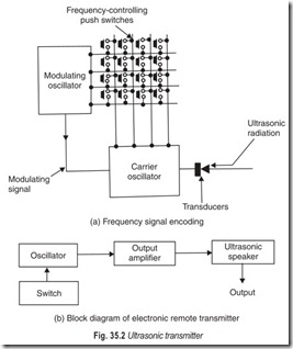
The receiving part of the remote control system receives the particular command signal transmitted by the remote transmitter and the required operation is carried out. The receiver contains a crystal matched to that in the transmitter and also a number of tuned circuits which respond to the different frequencies transmitted. The ultrasonic signal is sensitive to external noise. To overcome this drawback, different methods of encoding the signal can be used. One of them is the frequency signal encoding.
In the system, Fig. 35.2 (a) the transmitter uses two separate oscillator. One of the oscillator generates a carrier wave and the other, a modulating signal. By a slight variation in the tuning circuit, the carrier oscillator can produce four or more different frequencies, e.g. 35.43 kHz, 38.29 kHz, 41.15 kHz and 44.01 kHz. Similarly, the other oscillator, for generating modulating signal, can produce 148 Hz, 193 Hz, 254 Hz or 333 Hz. A modulating signal amplitude modulates any one of the four carrier frequencies depending upon the remote operation required. In this way, one would be able to select any of the 16 frequency combinations for transmission by a 4 × 4 matrix of push button switches. Each frequency combination represents a specific instruction.
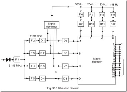
In the ultrasonic receiver (Fig. 35.3), a narrow bandpass filter (F1) allows only those signals whose frquencies lie within 35 kHz to 45 kHz range. All such signals are then applied to four more narrow band- pass filters (F2 to F5), only one of which will allow the frequency, already accepted by F1, to pass. Thus, these filters act as signal sorts ensuring that the desired signal is always routed to its correct terminal on the matrix decoder.
On leaving F2–F5, the desired signal is rectified by one of the four detectors D1–D4. It is then applied without H.F. filtering to any one of the detector-integrators D5 to D8, and to the signal-combiner unit. Since a detector integrator can produce an output only if it receives the correct input, a rectified signal at the input of a particular detector-integrator produces a dc signal at its output. This signal is applied to the appropriate terminal of the matrix decoder as a carrier identifier. It is now necessary to determine which of the four possible modulating frequencies is being applied to the identified carrier. This is the purpose of the signal combiner and of the four filters F6 to F9.
The signal combiner accepts any of the rectified, but unfiltered, modulated carriers derived from detectors D1–D4 and feeds the one it receives simultaneously to the four narrow-bandpass filters F6–F9. Only one of these filters will allow the modulating signal of the received carrier to pass, and so only one of the four possible modulating signals will be allowed to reach the detector integrator, D9–D12.
These operate in the same way as D5–D8, producing at their outputs dc signals corresponding to one particular modulating frequency. These dc signals are applied to the appropriate terminals of the matrix decoder as modulation identifiers. From these two identifiers the matrix decoder produces a signal at one of its 16 output terminals.
PULSE POSITION MODULATION ENCODING
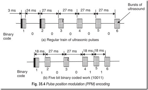
Pulse position modulation (PPM) encoding is the system where encoding is carried out by positioning the pulses. In the PPM method of signal encoding, the transmitted signal takes the form of a binary coded word formed from a succession of short bursts of ultrasound. Ultrasound frequencies are not included in the code. The code is determined by the time interval or space between successive ultrasound bursts. This principle is illustrated in Fig. 35.4. Here the frequency of ultrasound is 40 kHz.
In Fig. 35.4 (a), a regular train of six ultrasonic pulses, each of duration 3 ms, is repeated at 27 ms intervals. The separation rate is therfore 1000/27 or 37 Hz and the separaton time from trailing edge to leading edge is 24 ms. Suppose that the pulse separation interval of less than 20 ms is recognised by the receiver as binary-1 and more than 20 ms recognised as binary-0. Six equally spaced ultrasonic bursts with spacing interval greater than 20 ms represent five-bit binary code 0 and therefore identified by the notation 00000.
In Fig. 35.4 (b), five-bit binary coded word is identified by notation 10011 since the first, fourth and fifth pulse spacings are less than 20 ms and the second and third spacings are more than 20 ms.
For example, the PLESSY IC SL490 is a low power remote-control transmitter capable of driving a fixed frequency ultrasonic transducer by using the technique of PPM for signal encoding, and an 8 × 4 push switch matrix to provide up to 32 commands.
ENCODING BY TIME RATIO DISCRIMINATION
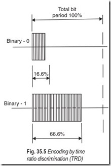
Time ratio discrimination (TRD) is also known as pulse width modulation (PWM). Despite coding taken as spacing between the pulses, the width of the pulses is taken here for identification of binary notation. Therefore, every bit of transmitted word is allocated a period of time within which the burst of ultrasound representing the bit must be transmitted. The actual duration of the transmitted bit is then expressed as a percentage of the allocated bit period, and the different percentages which result are used to represent binary-0 and binary-1.
The Philips SAA–05000A type remote-control transmitter is based on time ratio discrimination type of signal encoding. The principle of TRD is illustrated in Fig. 35.5. For example, binary- 1 is represented by a burst of ultrasound whose duration is 66.6% of the total bit period. The binary-0 is represented by a burst duration of 16.6% of the total bit period.
REMOTE CONTROL TRANSMITTER
The SAA–5000A is a MOS N-channel IC which provides the encoding and modulation function for the remote control of television receivers, including those equipped with Teletext and Viewdata facilities. The internal block diagram of IC–SAA 5000A is shown in Fig. 35.6. The transmitter using SAA–5000A is based on the time ratio discrimination encoding system. It provides 32 commands which are activated by switch controls on the keyboard matrix. The IC is connected to this keyboard by six matrix outputs and six matrix inputs.
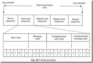
It utilises the TRD method of word encoding. It trasmits a 24 bit code for every transmitted command. It consists of a 7 bit “Start-Code” followed by a 5 bit “Message”. At the end of the message code, all the 12 bits of “start” and “message” code are retransmitted but this time with their individual bits inverted. Thus, the total transmitted word consists of 24 sequential bits, the last 12 of which are mirror images or complements of the first 12. The entire transmitted 24 bit word is repeated till the switch of the keypads remains depressed.
The advantage of sending 12 bit “start” and “message” code followed by 12 bit “complementary code” is that the receiver is easily able to distinguish the required code from external noise. Figure 35.7 explains the TRD word-coding sequence. The message code shown is the binary number 10001, but it could be any one of 32 combinations in all.The IC SAA–5000A is suitable forultrasonic and infrared transmission modes.
DESCRIPTION OF ULTRASONIC TRANSMITTER CIRCUIT
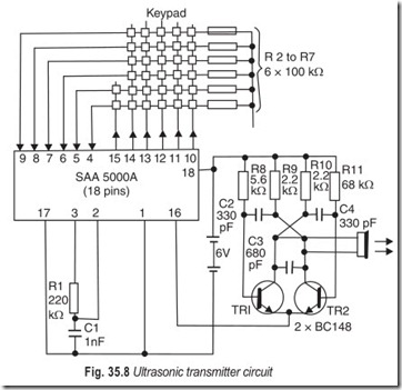
The ultrasonic transmitter circuit is shown in Fig. 35.8. The transmitter accepts data from the 32-keypads and coverts it into a 24–bit TRD-encoded word. The encoded data appears as a sequential switching waveform at pin 16 of the IC. It is used to turn ON and OFF the stable multivibrator, formed by the two transistors Q1 and Q2 and the associated components.
When the multivibrator is turned ON, it operates at a frequency of 40 kHz and is used to drive the ultrasonic transducer.
The bit period of the encoded word is determined by an oscillator within the IC whose operating frequency is set by the 220 kΩ resistor and 1000 pF capacitor connected externally to pins 2 and 3.
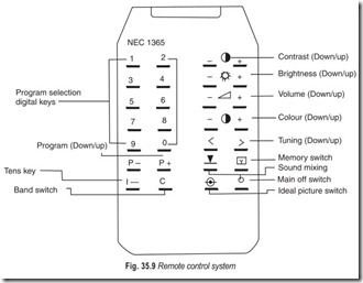
With the values shown in Fig. 35.8, the bit period would be about 82 ms but it can be varied over the range 0.8 ms to 10 ms. Pin 17 of the IC is shown connected to pin 1, which in turn, is connected to the negative electrode of the internal battery. This puts the IC into ultrasonic operating mode. A typical remote control system is illustrated in Fig. 35.9.
TROUBLE SHOOTING REMOTE CONTROL SYSTEMS
The trouble shooting assumption that a defect is the cause of a symptom is also used in servicing a remote system. The steps for isolating the defective component depend on the specific system. In general, the first step is to check whether the receiver operates in the manual mode. If it does, the trouble is in the remote control system. If the manual system is also non-operative, the fault lies with the set, in which case, the set should be serviced.
The remote system consists of a number of sections and/or modules. The transmitter can be checked by replacing it with another one in a working condition. If the transmitter is the cause of the trouble, check the battery and verify the frequencies. Mechanical transmitters are often damaged by rough handling and ideally should be replaced rather than repaired. If battery replacement does not help, check the components of the electronic transmitter. Since there are only one or two stages, part checking and replacement should help locate the defective part quickly.
If a receiver operates by manual control but not by the remote, and if even some other working transmitter does not operate it, then the trouble has to be in the remote receiver. In trouble-shooting, it is important to obtain as much information from the symptoms as possible. Thus, all the remote functions should be tried. If some functions operate and others do not, then the trouble probably lies in the connections or in the activating device for the inoperative functions. If none of the functions operate, this means the trouble is in a common section such as the transducer pick-up or the broad band amplifier. An accurate broad band audio generator can be used as a signal substitute to feed a signal directly to the remote receiver for signal-tracking. Here, a problem often overlooked is the possibility of overloading the remote receiver with some very strong, unrelated signal (e.g. the horizontal sweep signal). The remote receiver must be located at the correct point in the chassis and all shielding must be in place. If it seems that the horizontal signals are interfering with the remote control, disable the horizontal section and monitor the operation of the remote receiver by checking the voltage change at the output of the function that is being activated.
The technician must be familiar with the normal operation of the system. Some receivers have preset positions where colour, tint, brightness and contrast are set to a fixed value when the automatic system is activated. Under this condition, the remote tint control, for example, will have no effect. This is normal and not a defect. The automatic setting must be shut off in order to permit the remote functions to operate. As another example, in some digital systems the channel number must be entered from a keyboard, one digit at a time. Suppose if channel 7 is desired, then the digits 07 must be entered. If only the key 7 is pressed the receiver will automatically shut off after about 15 seconds. This safety feature prevents the receiver from being turned on by some accidental ultrasonic noise. Just as it is important to know the details of the system, so also it is necessary to teach the user proper operating procedures to prevent nuisance service calls caused by a lack of knowledge or by misunderstanding.
Most remote systems are modularised, allowing module substitution for quickly locating a defective module. A defective module can then be serviced in the shop or sent back to the factory for exchange. The use of modules requires many interconnections. Plugs and sockets do not always make a good contact. One simple remedy is to plug the module in and out several times. The contact wiping action resulting from this procedure may eliminate a poor connection. Cables are used for many interconnections. The dress of these cables may be critical to prevent feedback or pick-up. Moreover, these cables should not be permitted to rest on hot components because the insulation may melt. Repeatedly moving these cables can also cause individual wires to break, usually near the plug or socket. This type of problem may frequently be spotted by visual inspection, which must always be a part of the early service procedure.
The proper position of the microphone is important for a normal pick-up of ultrasonic energy. The microphone often fits into a housing on the front panel. It may be jarred loose by transportion or by carelessness after an unrelated repair. It is necessary to check all receiver functions after any repair.
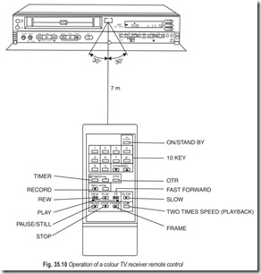
The operation of a typical colour TV receiver remote control is illustrated in Fig. 35.10 Note that the Mains Switch must be in the ON postion for the remote control unit to function.
REMOTE CONTROL OPERATION
Remote control button functions:
Each function of the remote control except for the SLOW, 10 key and two times speed playback function corresponds to those of the buttons provided on the front panel of the VTR. You can operate 27 functions in all by using the remote control unit which contain CHANNEL UP/DOWN, 10 key (direct channel selection), ON/STANDBY, RECORD, REWIND, FAST FORWARD, PICTURE SEARCH (FORWARD, REVERSE),
PLAY, PAUSE/STILL, SLOW, STOP, FRAME, OTR, TIMER and two times speed playback modes.
The remote control must have “Line of Sight” to the INFRARED REMOTE control receiver on the front of the VTR. It must be within an angle of 30° either side of centre. When you use the remote control unit while aiming it at the front side of the VTR, the maximum operating distance is about 7 m (within 30° either side of centre, the effective operating distance is approximately 5 m).
EXERCISES
Descriptive Questions
1. Describe the working of an ultrasonic transducer.
2. Explain the working of a remote transmitter with the help of a block diagram.
3. Explain the working of an ultrasonic receiver.
4. Differentiate between PPM and TRD methods of encoding.
Fill in the Blanks
1. One convenient feature of TV receivers is their…………………………… operation.
2. Remote control is a system by which one is able to…………………………… the performance of an equipment placed at a…………………………… .
3. Many TV receivers have provisions for operating the…………………………… remotely from a normal viewing distance.
4. The remote system has three main components a sremote transmitter, a remote receiver and the devices at the receiver to effect the change ordered by the remote…………………………… .
5. The line of sight and the approximate…………………………… of the transmitter become important only at the maximum range.
6. Each frequency combination represents a specific…………………………… .
7. In the PPM method of signal encoding the transmitted signal takes the form of a coded word formed from a succession of short bursts of…………………………… .
8. In TRD the…………………………… of the pulses is taken for identification of binary notation.
ANSWERS
Fill in the Blanks
1. remote 2. control, distance
3. ON-OFF, volume, maintuning, picture contrast, and brightness adjustments
4. command 5. aiming 6. instruction
7. binary, ultrasound 8. width

