Thermal Overload Relays
There are two major types of overload relays: thermal and magnetic. Thermal overloads operate by connecting a heater in series with the motor. The amount of heat produced is dependent on motor current. Thermal overloads can be divided into two types: solder melting type or solder pot, and bimetal strip type. Since thermal overload relays operate on the principle of heat, they are sensitive to ambient (surrounding air) temperature. They will trip faster when located in a warm area than they will in a cool area.
Solder Melting Type
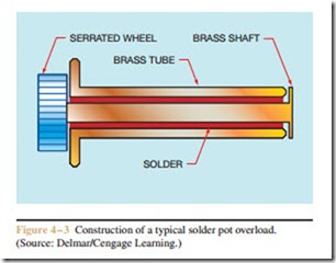
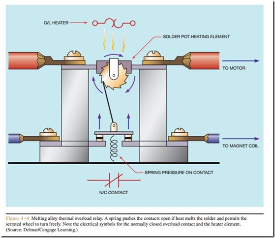
Solder melting type overloads are often called sol- der pot overloads. To create this type of overload, a brass shaft is placed inside a brass tube. A serrated wheel is connected to one end of the brass shaft. A special alloy solder that melts at a very specific temperature keeps the brass shaft mechanically connected to the brass tube (Figure 4 – 3). The serrated wheel keeps a set of spring loaded contacts closed (Figure 4 – 4). An electric heater
is placed around or close to the brass tube. The heater is connected in series with the motor. Motor current causes the heater to produce heat. If the current is great enough
for a long enough period of time, the solder will melt and permit the brass shaft to turn inside the tube, causing the contact to open. The fact that some amount of time must elapse before the solder can become hot enough to melt provides the time delay for this overload relay. A large overload will cause the solder to melt faster and cause the contacts to open more quickly than a smaller amount of overload current.
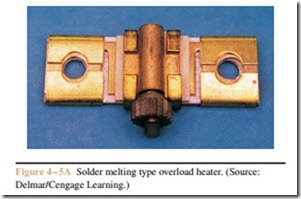
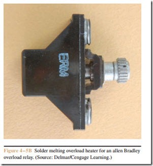
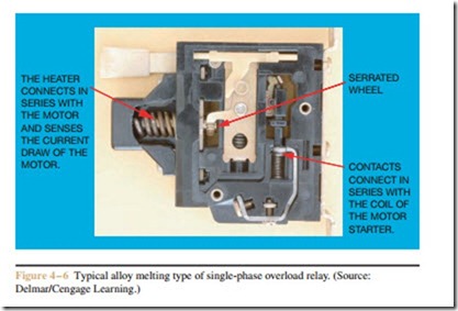
Solder melting type overload heaters are constructed differently by different manufacturers, but all work on the same principle. Two different types of melting alloy heater assemblies are shown in Figure 4 – 5, parts A and B. A typical melting alloy type overload relay is shown in Figure 4 – 6. After the over- load relay has tripped, it is necessary to allow the relay to cool for two or three minutes before it can be reset. This cool-down time is necessary to permit the solder to become hard again after it has melted.
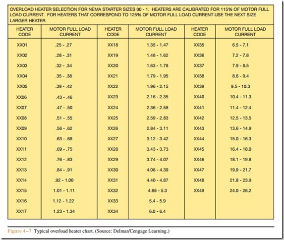
The trip current setting can be changed by changing the heater. Manufacturers provide charts that indicate what size heater should be installed for different amounts of motor current. It is necessary to use the chart that corresponds to the particular type of overload relay. Not all charts present the information in the same manner. Be sure to read the instructions contained with the chart when selecting heater sizes. A typical over- load heater chart is shown in Figure 4 – 7.
Bimetal Strip Overload Relay
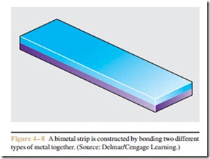
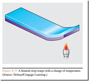
The second type of thermal overload relay is the bimetal strip overload. Like the melting alloy type, it operates on the principle of converting motor current into a proportionate amount of heat. The difference is that the heat is used to cause a bimetal strip to bend or warp. A bimetal strip is made by bonding together two different types of metal that expand at different rates (Figure 4 – 8). Since the metals expand at different rates, the strip will bend or warp with a change of temperature (Figure 4 – 9). The amount of warp is determined by:
1. The type of metals used to construct the bimetal strip.
2. The difference in temperature between the two ends of the strip.
3. The length of the strip.
The overload heater heats the bimetal strip when motor current flows through it. The heat causes the
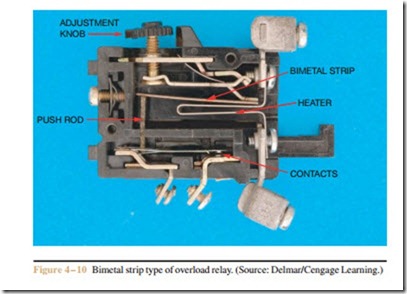
bimetal strip to warp. If the bimetal strip becomes hot enough, it will cause a set of contacts to open (Figure 4 – 10). Once the overload contact has opened, about 2 minutes of cool-down time is needed to permit the bimetal strip to return to a position that will permit the contacts to be re-closed. The time delay factor for this overload relay is the time required for the bimetal strip to warp a sufficient amount to open the normally closed contact. A large amount of overload current will cause the bimetal strip to warp at a faster rate and open the contact sooner.
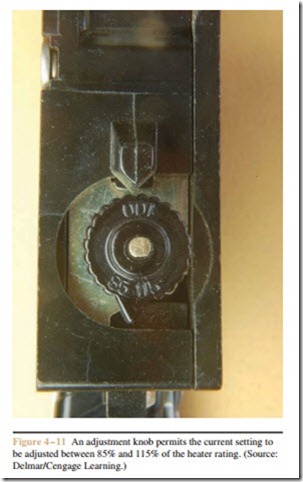
Most bimetal strip type overload relays have a couple of features that are not available with solder melting type overload relays. As a general rule, the trip range can be adjusted by turning a knob, as shown in Figure 4 – 10. This knob adjusts the distance the bimetal strip must warp before opening contacts. This adjust- ment permits the sensitivity to be changed due to changes in ambient air temperature. If the knob is set in the 100% position (Figure 4 – 11), the overload operates at the full load current rating as determined by the size of overload heater installed. In cold winter months, this setting may be too high to protect the motor. The knob can be adjusted in cold conditions to operate at any point from 100% to 85% of the motor full load current. In hot summer months, the motor may “nuisance trip” due to high ambient temperatures. For hot conditions, the adjustment knob permits the overload relay to be adjusted between 100% and 115% of motor full load current.
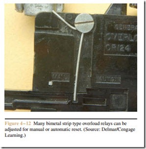
Another difference from the solder melting type is that many bimetal strip type overload relays can be set for either manual or automatic reset. A spring located on the side of the overload relay permits this setting (Figure 4 – 12). When set in the manual position, the contacts must be reset manually by pushing the reset lever. This is probably the most common setting for an overload relay. If the overload relay has been adjusted for automatic reset, the contacts will re-close by them- selves after the bimetal strip has cooled sufficiently. This may be a safety hazard if it could cause the sudden restarting of a machine. Overload relays should be set
in the automatic reset position only when there is no danger of someone being hurt or equipment being dam- aged when the overload contacts suddenly re-close.
Three-Phase Overloads
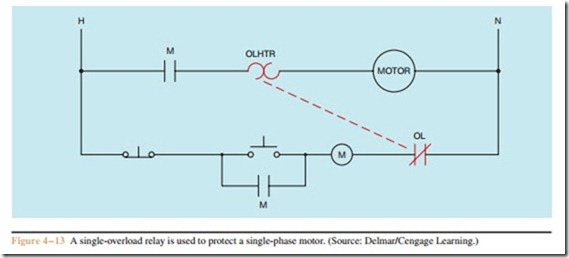
The overload relays discussed so far are intended to detect the current of a single conductor supplying power to a motor (Figure 4 – 13). An application for this
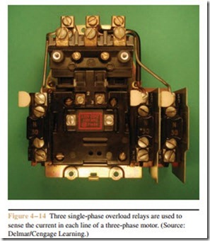
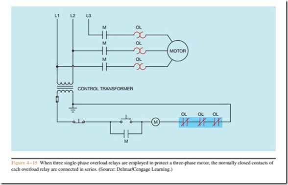
type of overload relay is to protect a single-phase or direct current motor. NEC requires only one overload sensor device to protect a direct current motor or a single-phase motor, whether it operates on 120 or 240 volts. Three-phase motors, however, must have an overload sensor (heaters or magnetic coils) in each of the three-phase lines. Some motor starters accomplish this by employing three single-overload relays to independently sense the current in each of the three-phase lines (Figure 4 – 14). When this is done, the normally closed contact of each overload relay is connected in series as shown in Figure 4 – 15. If any one of the relays should open its normally closed contact, power to the starter coil is interrupted and the motor is disconnected from the power line.
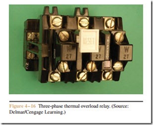
Overload relays are also made that contain three overload heaters and one set of normally closed contacts, Figure 4 – 16. These relays are generally used to protect three-phase motors. Although there is only one set of normally closed contacts, if an overload occurs on any one of the three heaters it causes the contacts to open and disconnect the coil of the motor starter (Figure 4 – 17).
Related posts:
Incoming search terms:
- overload relay selection chart
- overload relay range selection chart
- types of overload relay
- overload relay types
- how is time delay obtained in a bimetal type overload
- A molten-alloy overload element uses a _____ soldered to the conductor with a special alloy
- type of overload relay
- two major types of thermal overloads
- types of overloads
- types and selection criteria of overload relay in electric motor protection
- 22630982 overload relay
- types of overload
- how a soder pot heater works
- thermal overload relay rating chart
- Thermal types of overloads
- relay overload chart
- Thermal overload devices operate by magnetism
- overload relay rating chart
- Thermal overload can be divide into two types
- overload relay sizing chart
- overload relay standard range
- overload relay ta
- the solder-meting type of overload
- the solder-melting type of overload
- solder pot type relay
- Overload relays do no require a means of detecting current because of the bi-metallic element they posess True False
- solder pot thermal overload
- RQ26 Which of the following types of overloads gives the fastest response time to an overload condition? a magnetic b current c line break d electronic
- relay chart
- how time delay is obtained in this thermal overload relay
- overload relay chart
- overload relay are of which type
- For overloading protection of any apparatus the most common type of relay would be 1 point
- explain time delay in thermal type overload relay
- electrical overload type
- electrical overload relay ranges chart
- different type ofoverload relay and its application
- diferent types of over load re
- automatic uses of solder melting type relay
- an overload relay is capable of being reset once the overload is removed
- What type of thermal overload relay can generally be set for manual or automatic operation?
- how time delay obtained with a bi metal type overload
- overload heater metal used
- over load relaychart
- name two types of thermal overload relays
- motor overload relay rang chart
- motor overload protection chart
- motor over load chat
- major types of thermal overload relays
- list two types of thermal overload
