Nameplate data-for better motor installation and maintenance
By E.J. FELDMAN, Senior Application Engineer, Siemens-Allis, Inc. , Norwood , OH
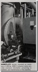
MOTOR NAMEPLATES provide a great deal of useful design and per formance data. This information is particularly valuable to installers and to faci lity electrical personnel who maintain and rep lace existing motors. During installation, maintenance or replacement, the information on the nameplate is vital to fast and proper performance of the job at hand.
NEMA Publication MG1, Section 10.38, states that the following data should be stamped on every motor nameplate: Manufacturer , Type, Frame, Horsepower, Time Rating, Ambient Temperature, RPM, Frequen cy, Phases, Rated Load Amps, Voltage, Locked Rotor Code Letter, Design Let ter, Service Factor and Insulation Class. In addition, the motor manufac turer may include such data as his name and manufacturing plant loca tion and individual identification.
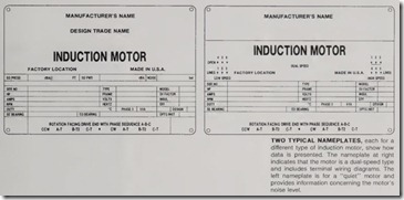
Most data given on the nameplate refers to electrical characteristics of the motor; therefore it is important for the installer/maintainer to be a quali fied plant electrician/ engineer or an industrial-oriented electrical contractor. For a better understanding of this data, two typical nameplates are illus trated here. The following discussion provides an explanation of the im printed notations.
Serial Number: This is the individual, unique number assigned to this spe cific motor or design for identification should it be necessary to communicate with the manufacturer for any reason.
Type: The combination of letters and/or numbers chosen by the manu facturer identifies the type of enclosure and any significant modification there of. It is necessary to have each manu facturer’s coding system to understand the meaning.
Model Number: Additional identifi cation data for manufacturer.
Hors epoUJer: Rated horsepower is the horsepower the motor was designed to deliver at its shaft with rated fre quency and voltage applied to the ter minals with a service factor of 1.0.
Frame: Frame size designation iden tifies the dimensions of the motor. If it is a NEMA frame, it identifies the mounting dimensions (given in MGI ) so that the manufacturer’s dimen sioned drawings are not required.
Service Factor: The most common service factors are 1.0 to 1.15. If it is 1.0, it means that the motor should not be required to deliver greater than rated horsepower if injury to the insu lation system is to be avoided. For 1.15 (actually, any value above 1.0), the motor may be run at a horsepower equal to rated horsepower times this service factor without serious injury to the insulation system. However, it should be pointed out that continuous operation within the service factor range will result in shortening the life expectancy of the insulation system.
Amps: The current drawn by the motor at rated voltage and frequency with full rated horsepower delivered to the load will be stamped in this space.
Volts: The design value of voltage is stamped in this space. This should be the value as measured at the terminals of the motor rather than the voltage of the supply line. Standard voltages are given in MG1-10.30.
Class of Insulation: The class of insulating materials used in winding the stator is given here. These are systems of materials that have been extensively tested for long life exposed to preset temperatures. Class B system maximum operating temperature is 130° C; Class F system is 155° C; and Class H is 180° C.
RPM· This is the speed of the output shaft when delivering rated horsepow er to the driven device with rated volt age and frequency applied to the terminals of the motor.
Hertz: This is the frequency of the supply system for which the motor is designed. Motors can operate at other frequencies, but performance will be altered.
Duty: Either “Intermittent” or “Continuous” is stamped in this space. If “Continuous,” it means that the motor can be run 24 hrs/day, 365 days/year for many years. If “Inter mittent,” a time interval will be shown. This means the motor can operate at full load for the time interval given. After that time, the motor must be de-energized and allowed to cool before restarting.
Temperature Ambient: This speci fies maximum ambient temperature, in O C, at which the motor can safely deliv er rated horsepower. If ambient is higher than the stamped value, the motor output must be derated to pre vent injury to the insulation system.
Phase: This entry indicates the num ber of phases for which the motor is designed. It must match the supply system.
k VA Code: The starting inrush cur rent can be determined from this space. It is specified as a code letter indicating a range of kVA/hp. The range for each letter is specified in NEMA MG1-10.36. A common value is Code G, which covers a range of 5.6 up to, but not including, 6.3 kVA/hp. It is necessary to check the starting equip ment for design compatibility as well as the local power company acceptance of this load on their system.
Design: When applicable, the NEMA design letter is stamped in this space. This letter specifies minimum torque values at locked rotor, pull-up and break-down speeds, and maximum inrush current and maximum rated load slip value. These values are speci fied in NEMA MG1, Sections 1.16 and 1.17.
Bea.rings: For motors supplied with antifriction bearings, the bearings are identified by stamping the appropriate sequence of numbers and letter per AFBMA (Anti-Friction Bearing Man ufacturers Assn.) Standards. Thus, the bearings can be replaced with the origi nal design should replacement be nec essary, since the AFBMA number includes the looseness of the bearing fit, the type of retainer, the degree of protection (shielded, sealed, open, etc., as well as the dimensions. Both the shaft end (SE) and end opposite (EO) the shaft bearings are designated.
Phase Sequence: The inclusion of phase sequence markings on the name plate enables the installer to connect the motor for the designed rotation on the first attempt assuming the phase sequence of the supply line is known. If the supply sequence is A-B-C, connect leads as given on plate. If sequence is A-C-B, connect them opposite to that shown on the plate.
External connections are usually not shown on the nameplates of single speed, 3-lead motors. However, for motors with more than three leads, the external connections are shown on the nameplate. Note that the nameplate for the dual-speed motor shows connec tions for low speed and for high speed. To run on low speed, line 1 must be connected to the motor lead T-1, line 2 to T-2, and line 3 to T-3, with motor leads T-4, T-5 and T-6 remaining open. For operation at high speed, connect line 1 to T-6, line 2 to T-4, and line 3 to T-5, with T-1, T-2, and T-3 shorted together.
Efficiency: This space will be marked with the NEMA nominal effi ciency of the motor, which is derived from Table 12-4 of MG 1-12.53b. This efficiency data is applicable to “stan dard” motors as well as to “premium efficiency” motors. Those special design, “energy-efficient” motors will be marked as such on the nameplate.
Low Noise: Some motors are de signed for low noise emission. There fore, the noise level is given on the nameplate expressed both as sound power and sound pressure. Both are measured in “dbA” units. This means the sound output from the motor has been fed through an “A” weighting network of filters which approximates the sound as perceived by the human ear. Since sound pressure has directiv Sound power is a measure of the total energy emitted by the source. It is preferred for acoustical analysis since it can be combined mathematically with other sound sources to determine overall levels.
Noise emission is another way of stating the sound power in u·nits out lined in Acoustical Society of America Standard 5-1976, which also references ANSI Spec. 51.23-1976.

