INDUSTRIAL VALVES
An industrial valve is a device that controls not only the flow of a fluid, but also the rate, volume, pressure or direction of liquids, gases, slurries, or dry materials through a pipeline, chute, or similar passageway. Using valves, the flow of a fluid in various passageways can be turned ON and OFF, regulated, modulated, or isolated. The size range available is huge from a fraction of an inch to as large as 30 ft in diameter, and they can vary in complexity from a simple brass valve available at a hardware store, to a precision-designed, highly sophisticated coolant system control valve, made of an exotic metal alloy to be used in a nuclear reactor. Industrial valves can control the flow of all types of fluid, from the thinnest gas to highly corrosive chemicals, superheated steam, abrasive slurries, toxic gases, and radioactive materials. In addition, they can handle temperatures from the cryogenic region to those of molten metal, and pressures from high vacuum to thousands of pounds per square inch.
Control valves
The final control element is the device that implements the control strategy determined by the output of the controller. This can be a damper or a variable speed drive pump or an ON OFF switching device, but the most commonly occuring is the control valve. It is the kind of final element that manipulates a flowing fluid, such as gas, steam, water, or chemical compound, so as to compensate for load disturbances and keep the regulated process variable as close as possible to the desired set point.
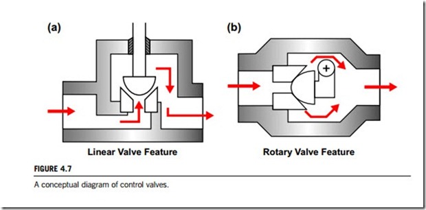
Control valves really refer to a control valve assembly. This typically consists of the valve body, internal trim parts, an actuator to provide the motive power to operate the valve, and a variety of additional valve accessories, which can include positioners, transducers, supply pressure regulators, manual operators, snubbers, or limit switches. Figure 4.7 gives two conceptual diagrams for the linear and rotary control valve assembly, respectively. The interested reader can identify the valve body, the internal trim parts, and an actuator in this diagram.
The control valve regulates the rate of fluid flow as the position of the valve plug or disk is changed by force generated by the actuator. To do this, the valve must contain fluid without external leakage; have adequate capacity for the intended service; be capable of withstanding the erosive, corrosive and temperature influences of the process; and incorporate appropriate end connections to mate with adjacent pipelines. The actuator attachment must transmit the actuator thrust to the valve plug stem or rotary shaft.
(1) Basic types
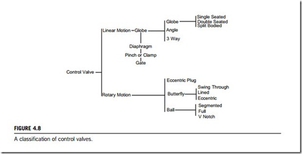
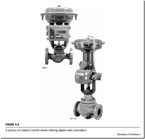
Many styles of control valve bodies have been developed through the years. Some have found wide application; others meet specific service conditions and are used less frequently. Figure 4.8 is a classification of control valves used in today’s industrial controls. Figure 4.9 is a product picture of a special control valve.
The following summary describes some popular control valve body styles currently, in use some special application valves, steam conditioning valves, and ancillary devices including valve actuators, positioners, and accessories.
(1) Linear globe valves
Linear globe valves have a linear motion closure member, one or more ports, and a body distinguished by a globular-shaped cavity around the port region. Globe valves can be divided into single-ported valve bodies, balance-plug cage-guided bodies, high-capacity cage-guided valve bodies, port-guided single-port valve bodies, double-ported valve bodies, and three-way valve bodies.
(2) Rotary shaft valves
Rotary shaft valves have a flow closure member (full ball, partial ball, disk, or plug) is rotated in the flow stream to control the capacity of the valve. Rotary shaft valves can be further classified as butterfly
valve bodies, V-notch ball control valve bodies, eccentric-disk control valve bodies, and eccentric-plug control valve bodies.
(3) Special valves
Standard control valves can handle a wide range of control applications, but corrosiveness and viscosity of the fluid, leakage rates, and many other factors demand consideration even for standard conditions. The following discusses some special control valve modifications that are useful in severe controlling applications.
(a) High-capacity control valves including globe style valves larger than 12-inch, ball valves over 24-inch, and high-performance butterfly valves larger than 48-inch. As valve sizes increase arithmetically, static pressure loads at shutoff increase geometrically. Consequently, shaft strength, bearing loads, unbalance forces, and available actuator thrust all become more significant with increasing valve size. Normally, maximum allowable pressure drop is reduced on large valves to keep design and actuator requirements within reasonable limits. Even with lowered working pressure ratings, the flow capacity of some large-flow valves remains tremendous.
(b) Low-flow control valves. Many applications exist in laboratories, pilot plants and the general processing industries where control of extremely low flow rates is required. These applications are commonly handled with special trim which is often available in standard control valve bodies. This is typically made up of a seat ring and valve plug that have been designed and machined to very close tolerances, in order to allow accurate control of very small flows.
(c) High-temperature control valves. These control valves are specially designed for service at temperatures above 450oF (232oC). They are encountered in boiler feed water systems and super- heater bypass systems.
(d) Cryogenic service valves. These can cope with materials and processes at temperatures below -150oF (-101oC). Many of the same issues need consideration for cryogenic conditions as with high- temperature control valves. Packing is a concern in cryogenic applications, since plastic and elec- trometric components often cease to function appropriately at temperatures below 0oF (-18oC). For plug seals, a standard soft seal will become very hard and less pliable, thus not providing the shut-off required. Special electrometrics have been applied in these temperatures, but require special loading to achieve a tight seal.
(4) Steam conditioning valves
A steam conditioning valve is used for the simultaneous reduction of steam pressure and temperature to the level required for a given application. Frequently, these applications deal with high inlet pressures and temperatures and require significant reductions of both properties. They have forged and fabricated bodies that can better withstand steam loads at elevated pressures and temperatures. Forged materials can withstand higher design stresses, have improved grain structure, and an inherent material integrity over cast valve bodies. The forged construction also allows the manufacturer to provide up to Class 4500, as well as intermediate and special class ratings, with greater ease vs. cast valve bodies.
Due to extreme and frequent changes in steam properties as a result of the temperature and pressure reduction, the forged and fabricated valve body design allows for the addition of an expanded outlet to control outlet steam velocity at lower pressure. Similarly, with reduced outlet pressure, the forged and fabricated design allows the manufacturer to provide different pressure class ratings for the inlet and outlet connections to more closely match the adjacent piping.
The latest versions of steam conditioning valves have feed-forward, manifold, pressure reduction- only, or turbine bypass designs.
The turbine bypass system has evolved over the past few decades as the mode of power plant operations has changed. It is employed routinely in utility power plants, where quick response to wide swings in energy demand is needed. A typical power plant operation might start at minimum load, increase to full capacity for most of the day, rapidly reduce back to minimum output, and then up again to full load all within a 24-hour period. Boilers, turbines, condensers, and other associated equipment cannot respond properly to such rapid changes without some form of turbine bypass system. This system the boiler to operate independently of the turbine. In the start-up mode, or for a rapid reduction in demand, the turbine bypass not only supplies an alternative flow path for the steam, but conditions the steam to the same pressure and temperature that is normally produced by the turbine expansion process. By providing an alternative flow path for the steam, the turbine bypass system protects the turbine, boiler, and condenser from damage that may occur from thermal and pressure excursions. For this reason, many such systems require extremely rapid open/close response times for maximum equipment protection. This is accomplished by using an electrohydraulic actuation system, which provides both the forces and controls for such operation. Additionally, when commissioning a new plant, the turbine bypass system allows start-up and check-out of the boiler separately from the turbine. This allows quicker plant start-ups, which results in attractive economic gains. It also means that this closed-loop system can prevent atmospheric loss of treated feed water and reduction of ambient noise emissions.
(2) Valve actuators
Pneumatically operated control valve actuators are the most popular type in use, but electric, hydraulic, magnetic, and piezoelectric actuators are also popular. All these actuators were introduced in the previous chapter.
The spring-and-diaphragm pneumatic actuator is most commonly specified due to its depend- ability and simplicity of design. Pneumatically operated piston actuators provide high stem force output for demanding service conditions. Adaptations of both spring-and-diaphragm and pneumatic piston actuators are available for direct installation on rotary shaft control valves. Electric and electrohydraulic actuators are more complex and more expensive than pneumatic actuators, which offer advantages where no air supply source is available, where low ambient temperatures could freeze condensed water in pneumatic supply lines, or where unusually large stem forces are needed.
Pneumatically operated diaphragm actuators use the air supply from a controller, positioner, or other source. There are various styles; the direct action of increasing air pressure pushes down the diaphragm and extends the actuator stem; the reverse action of increasing air pressure pushes up the diaphragm and retracts the actuator stem; reversible actuators that can be assembled for either direct or reverse action; direct-acting unit for rotary valves where increasing air pressure pushes down on the diaphragm, which may either open or close the valve, depending on the orientation of the actuator lever on the valve shaft.
Piston actuators are pneumatically operated using high-pressure plant air to 150 psig, often eliminating the need for a supply pressure regulator. Piston actuators furnish maximum thrust output and fast stroking speeds. Piston actuators are double acting to give maximum force in either direction, or spring return to provide fail-open or fail-closed operation.
Electrohydraulic actuators require only electrical power to the motor and an electrical input signal from the controller. Electrohydraulic actuators are ideal for isolated locations where pneumatic supply pressure is not available, but where precise control of valve plug position is needed. Units are normally reversible by making minor adjustments and can be self-contained, including motor, pump, and double-acting hydraulically operated piston within a weatherproof or explosion-proof casing.
Rack and pinion designs provide a compact and economical solution for rotary shaft valves. Because of backlash, they are typically used for ON OFF applications, or where process variability is not a concern.
Traditional electric actuator designs use an electric motor and some form of gear reduction to move the valve. Through adaptation, these mechanisms have been used for continuous control with varying degrees of success. To date, electric actuators have been much more expensive than pneumatic ones for the same performance levels. This is an area of rapid technological change, and future designs may cause a shift toward greater use of electric actuators.
(3) Valve positioners
Positioners are used for pneumatically operated valves that depend on a positioner to take an input signal from a process controller and convert it into valve travel. These positioners are mostly available in three configurations:
1. Pneumatic. A pneumatic signal (usually 3 15 psig) is supplied to the positioner. The positioner translates this to a required valve position and supplies the valve actuator with the air pressure required to move the valve to the correct position.
2. Analog I/P. This positioner performs the same function as the one above, but uses electrical current
(usually 4 20 mA) instead of air as the input signal.
3. Digital. Although this positioner functions very much like the analog I/P described above, it differs in that the electronic signal conversion is digital rather than analog. The digital products cover three categories:
(a) Digital noncommunicating. A current signal (4 20 mA) is supplied to the positioner, which
both powers the electronics and controls the output.
(b) HART. This is the same as the digital noncommunicating, but is also capable of two-way digital communication over the same wires that are used for the analog signal.
(c) Fieldbus. This type receives digitally based signals and positions the valve using digital
electronic circuitry coupled to mechanical components.
(4) Valve accessories
Valve accessories include the following devices:
1. Limit switches. Limit switches operate discrete inputs to a distributed control system, signal lights, small solenoid valves, electric relays, or alarms. An assembly that can be mounted on the side of the actuator houses the switches. Each switch adjusts individually, and can be supplied for either alternating current or direct current systems. Other styles of valve-mounted limit switches are also available.
2. Solenoid valve manifold. The actuator type and the desired fail-safe operation determine the
selection of the proper solenoid valve. They can be used on double-acting pistons or single- acting diaphragm actuators.
3. Supply pressure regulator. Supply pressure regulators, commonly called airsets, reduce plant air
supply to valve positioners and other control equipment. Common reduced air supply pressures are 20, 35, and 60 psig. The regulator mounts integrally to the positioner or nipple-mounts or bolts to the actuator.
4. Pneumatic lock-up systems. Pneumatic lock-up systems are used with control valves to lock in
existing actuator loading pressure in the event of supply pressure failure. These devices can be used with volume tanks to move the valve to the fully open or closed position on loss of pneumatic air supply. Normal operation resumes automatically with restored supply pressure. Functionally similar arrangements are available for control valves using diaphragm actuators.
5. Fail-safe systems for piston actuators. In these fail-safe systems, the actuator piston moves to the
top or bottom of the cylinder when supply pressure falls below a predetermined value. The volume tank, charged with supply pressure, provides loading pressure for the actuator piston when supply pressure fails, thus moving the piston to the desired position. Automatic operation resumes, and the volume tank is recharged when supply pressure is restored to normal.
6. PC diagnostic software. PC diagnostic software provides a consistent, easy to use interface to every
field instrument within a plant. For the first time, a single resource can be used to communicate and analyze field electronic “smart” devices such as pressure xmtrs, flow xmtrs, etc., not pneumatic positioners, boosters. Users can benefit from reduced training requirements and reduced software expense. A single purchase provides the configuration environment for all products. Products and services are available that were not possible with stand-alone applications. The integrated product suite makes higher-level applications and services possible.
7. Electropneumatic transducers. The transducer receives a direct current input signal and uses a torque motor, nozzle flapper, and pneumatic relay to convert the electric signal to a proportional pneumatic output signal. Nozzle pressure operates the relay and is piped to the torque motor feedback bellows to provide a comparison between input signal and nozzle pressure.
Self-actuated valves
Self-actuated valves are those valves that use fluid or gas existing in a system to position the valve. Check valves and relief valves are two important examples of self-actuated valves. In addition, safety valves and steam traps are also defined as self-actuated valves. All of these valves are actuated with the system fluid or gas; no source of power outside the system fluid or gas energy is necessary for their operation.
(1) Check valves
Check valves are self-activating safety valves that permit gases and liquids to flow in only one direction, thus preventing process flow from reversing. When open and under flow pressure, the checking mechanism will move freely in the medium, offering very little resistance and minimal pressure drop. Check valves are classified as one-way directional valves; fluid flow in the desired direction opens the valve, while backflow forces the valve to close.
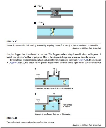
A check valve is hence a uni-directional valve for fluid flow. There are many ways to achieve such flow. Most check valves contain a ball that sits freely above the seat, which has only one through-hole. The ball has a slightly larger diameter than that of the through-hole. When the pressure behind the seat exceeds that above the ball, liquid flows through the valve; however, once the pressure above the ball exceeds the pressure below the seat, the ball returns to rest in the seat, forming a seal that prevents backflow.
Figure 4.10 is used here to describe briefly the principles of check valves. Device A (Figure 4.10(A))
consists of a ball bearing retained by a spring. Fluid flowing to the right will push the ball bearing against the spring, and open the valve to permit flow. This device requires some pressure to compress the spring and open the valve. If an attempt is made to flow fluid to the left, the ball bearing seals against the opening and no flow is allowed. This is a modern design that requires round balls. Device B (Figure 4.10(B)) is
while denying flow to the left. On the upward stroke, the pump fills from the left, while denying reverse flow from the right. The design in schematic B (Figure 4.11(B)) is somewhat different. The piston has one or more holes drilled though it, with a check valve on each hole. (One hole is illustrated.) On the downward stroke, the fluid moves from below the piston, to the chamber above the piston, and is denied exit to the left. On the upward stroke, fluid is pushed out the exit on the right and simultaneously more fluid is drawn from the entrance on the left. Case B is the design illustrated by Watt in his patent and described as the air pump, since it pumps air as well as water.
Check valves use a variety of technologies in order to allow and prevent the flow of liquids and gases. Single-disk swing valves are designed with the closure element attached to the top of the cap. Double-disk or wafer check valves consist of two half-circle disks that are hinged together, and fold together upon positive flow and retract to a full circle to close against reverse flow. Lift-check valves feature a guided disk. Spring-loaded devices can be mounted vertically or horizontally. Silent or center guide valves are similar to lift check valves, with a center guide extending from inlet to outlet ports. The valve stopper is spring and bushing actuated to keep the movement “quiet”. Ball check valves use a free-floating or spring-loaded ball resting in a seat ring as the closure element. Cone check valves use a free-floating or spring-loaded cone resting in the seat ring as the closure element. Although there are many types of check valves, two basic types are most popular in industrial control swing check valves and ball check valves. Both types of valves may be installed vertically or horizontally.
(1) Swing check valves
Swing check valves are used to prevent flow reversal in horizontal or vertical pipelines (vertical pipes or pipes in any angle from horizontal to vertical with upward flow only). Swing check valves have disks that swing open and closed. They are typically designed to close under their own weight, and may be in a state of constant movement if the pressure due to flow velocity is not sufficient to hold it valve in a wide-open position. Premature wear or noisy operation of the swing check valves can be avoided by selecting the correct size on the basis of flow conditions.
The minimum velocity required to hold a swing check valve in an open position is expressed by the empirical formula given by Figure 4.12, where V is the liquid flow measured in m/s or ft/s; v is the special volume of the liquid measured in m3/N or ft3/lb; j equals 133.7 (35) for Y-pattern, or 229.1 (60) for bolted cap, or 381.9 (100) for UL listed.
Tilting disk check valves are pivoted circular disks mounted in a cylindrical housing. These check valves have the ability to close rapidly, thereby minimizing slamming and vibrations. Tilting disk checks are used to prevent reversal in horizontal or vertical-up lines similar to swing check valves. The minimum velocity required for holding a tilting check valve wide open can be determined by the empirical formula given in Figure 4.12, where V is the liquid flow measured in m/s or ft/s; v is the special volume of the liquid measured in m3/N or ft3/lb; j equals 305.5 (80) for 5 times by disk angle (typically for steel), or ¼ 114.6 (30) for 15 times by disk angle (typical for iron).
Lift check valves also operate automatically by line pressure. They are installed with pressure under the disk. A lift check valve typically has a disk that is free-floating and is lifted by the flow. Liquid has an indirect line of flow, so the lift check restricts the flow. Because of this, lift check valves are similar to globe valves, and are generally used as companions to them.
(2) Ball check valves
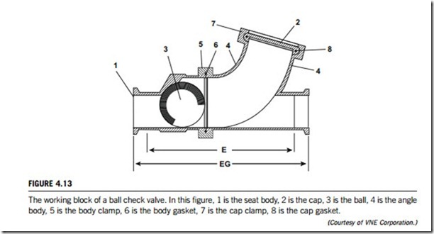
A ball check valve is a type of check valve in which the movable part is a spherical ball, as illustrated in Figure 4.13. Ball check valves are used in spray devices, dispenser spigots, manual and other pumps, and refillable dispensing syringes. Ball check valves may sometimes use a free-floating or spring- loaded ball.
Ball check valves generally have simple, inexpensive metallic parts, although specialized ball check valves are also available. For example, ball check valves in high-pressure pumps used in analytical chemistry have a ball of synthetic ruby, which is a hard and chemically resistant substance. A ball check valve is not to be confused with a ball valve, which is a quarter-turn valve similar to a butterfly valve in which the ball acts as a controllable rotor.
(2) Relief valves
A relief valve is a mechanism that ensures system fluid flow when a preselected differential pressure across the filter element is exceeded; the valve allows all or part of the flow to bypass the filter element. Relief valves are used in oil and gas production systems, compressor stations, gas transmission (pipeline) facilities, storage systems, in all gas processing plants, and whenever there is a need to exhaust the overpressure volume of gas, vapor, and/or liquid.
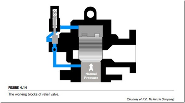
Figure 4.14 illustrates the working blocks of a relief valve, which operate on the principle of unequal areas being exposed to the same pressure. When the valve is closed, the system pressure
pushes upward against the piston seat seal on an area equal to the inside diameter of the seat. Simultaneously, the same system pressure, passing through the pilot, exerts a downward force on the piston, but this acts on an area approximately 50% greater than the inside diameter of the seat. The resulting differential force holds the valve tightly closed. As the system reaches the discharge pressure set for the valve, the piston seal becomes tighter, until the system pressure reaches the relief valve discharge set pressure. At that moment, and not before, the pilot cuts off the supply of system pressure to the top of the piston and vents that system pressure which is located in the chamber above the piston of the relief valve. At the same instant, the relief valve pops open. When the predetermined blow-down pressure is reached (either fixed or adjustable), the pilot shuts off the exhaust and reopens flow of system pressure to the top of the piston, effectively closing the relief valve.
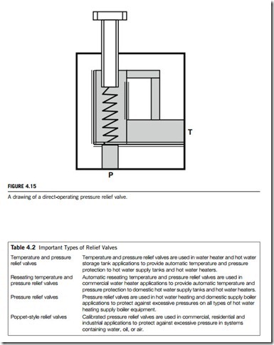
Figure 4.15 is a drawing of a direct-operating pressure relief valve. This pressure relief valve is mounted at the pressure side of the hydraulic pump that is located on its bottom. The task of this pressure relief valve is to limit the pressure in the system to an acceptable value. A pressure relief valve has infact the same construction as a spring-operated check valve. When the system becomes over- loaded, the pressure relief valve will open, and the pump flow will be led directly into the hydraulic reservoir. The pressure in the system remains at the value determined by the spring on the pressure relief valve. In the pressure relief valve, the pressure that is equal to the system energy will be con- verted into heat. For this reason pressure relief valves should not be operated for long durations.
Table 4.2 lists several important types of relief valve, categorized in terms of their applications. In industrial control, typical features for relief valves include the following:
1. Pressure settings of relief valves are externally adjustable while the valve is in operation. Most vendors of relief valves offer eight different spring ranges, to provide greater system sensitivity and enhanced performance.
2. Manual override option with positive stem retraction is available for pressures. This option permits the user to relieve upstream pressure while maintaining the predetermined cracking pressure.
3. Color-coded springs and labels indicate spring cracking range.
4. Lock-wire feature secures a given pressure setting.
Solenoid valves
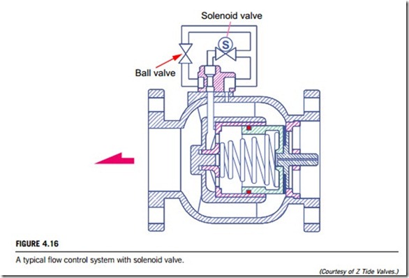
A solenoid control valve is a kind of isolation valve that is an electromechanical device allowing an electrical device to control the flow of gas or liquid. The electrical device causes a current to flow through a coil located on the solenoid valve, which in turn results in a magnetic field that causes the displacement of a metal actuator. The actuator is mechanically linked to a valve inside the solenoid valve. This mechanical valve then opens or closes and so allows a liquid or gas either to flow through, or be blocked by the solenoid valve. In this control system, a spring is used to return the actuator and valve back to their resting states when the current flow is removed. Figure 4.16 shows the application of a solenoid valve in a typical control system. A coil inside the solenoid valve generates a magnetic field once an electric current is flowing through. The generated magnetic field actuates the ball valve that can change states to open or close the device in the fluid direction indicated by the arrow.
Solenoid valves are used wherever fluid flow has to be controlled automatically, such as in factory automation. A computer running an automation program to fill a container with some liquid can send
a signal to the solenoid valve to open, allowing the container to fill, and then remove the signal to close the solenoid valve, and so stop the flow of liquid until the next container is in place. A gripper for grasping items on a robot is frequently an air-controlled device. A solenoid valve can be used to allow air pressure to close the gripper, and a second solenoid valve can be used to open the gripper. If a two-way solenoid valve is used, two separate valves are not needed in this application. Solenoid valve connectors are used to connect solenoid valves and pressure switches.
(1) Operating principles
Solenoid valves are control units which, when electrically energized or de-energized, either shut off or allow fluid flow. The actuator inside a solenoid valve takes the form of an electromagnet. When energized, a magnetic field builds up, which pulls a plunger or pivoted armature against the action of a spring. When de-energized, the plunger or pivoted armature is returned to its original position by the spring action.
According to the mode of actuation, a distinction is made between direct-acting valves, internally piloted valves, and externally piloted valves. A further distinguishing feature is the number of port connections or the number of flow paths or “ways”.
Direct-acting solenoid valves have the seat seal attached to the solenoid core. In the de-energized state, the seat orifice is closed, and opens when the valve is energized. With direct-acting valves, the static pressure forces increase with increasing orifice diameter, which means that the magnetic forces required for overcoming the pressure force become correspondingly larger. Internally piloted solenoid valves are therefore employed for switching higher pressures in conjunction with larger orifice sizes; in this case, the differential fluid pressure performs most of the work of opening and closing the valve.
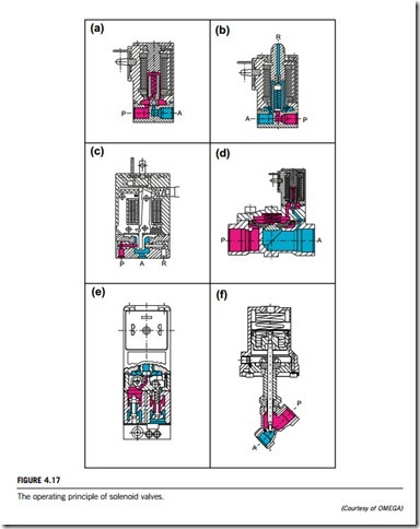
Two-way solenoid valves are shut-off valves with one inlet port and one outlet port, as shown in Figure 4.17(a). In the de-energized state, the core spring, assisted by the fluid pressure, holds the valve seal down on the valve seat to shut off the flow. When energized, the core and seal are pulled into the solenoid coil and the valve opens. The electromagnetic force is greater than the combined spring force and the static and dynamic pressure forces of the medium.
Three-way solenoid valves have three port connections and two valve seats. One valve seal always remains open and the other closed in the de-energized mode. When the coil is energized, the mode reverses. The three-way solenoid valve shown in Figure 4.17(b) is designed with a plunger-type core. Various valve operations are available, according to how the fluid medium is connected to the working ports. In Figure 4.17(b), The fluid pressure builds up under the valve seat. With the coil is de-energized, a conical spring holds the lower core seal tightly against the valve seat and shuts off the fluid flow. Port A is exhausted through R. When the coil is energized, the core is pulled in, and the valve seat at Port R is sealed off by the spring-loaded upper core seal. The fluid medium now flows from P to A.
Unlike the versions with plunger-type cores, pivoted-armature solenoid valves have all port connections inside the valve body. An isolating diaphragm ensures that the fluid medium does not come into contact with the coil chamber. Pivoted-armature valves can be used to obtain any three-way solenoid valve operation. The basic design principle is shown in Figure 4.17(c). Pivoted-armature valves are provided with manual override as a standard feature.
Internally piloted solenoid valves are fitted with either a two-way or a three-way pilot solenoid
valve. A diaphragm or a piston provides the seal for the main valve seat. The operation of such a valve is indicated in Figure 4.17(d). When the pilot valve is closed, the fluid pressure builds up on both sides of the diaphragm via a bleed orifice. As long as there is a pressure differential between the inlet and
outlet ports, a shut-off force is available by virtue of the larger effective area on the top of the dia- phragm. When the pilot valve is opened, the pressure is relieved from the upper side of the diaphragm. The greater effective net pressure force from below now raises the diaphragm and opens the valve. In general, internally piloted valves require a minimum pressure differential to ensure satisfactory opening and closing.
Internally piloted four-way solenoid valves are used mainly in hydraulic and pneumatic applications to actuate double-acting cylinders. These valves have four port connections; a pressure inlet P, two cylinder port connections A and B, and one exhaust port connection R. An internally piloted four/ two-way poppet solenoid valve is shown in Figure 4.17(e). When de-energized, the pilot valve opens at the connection from the pressure inlet to the pilot channel. Both poppets in the main valve are now pressurized and switch over. Now port connection P is connected to A, and B can exhaust via a second restrictor through R.
With these types an independent pilot medium is used to actuate the valve. Figure 4.17(f) shows a piston-operated angle-seat valve with closure spring. In the unpressurized condition, the valve seat is closed. A three-way solenoid valve, which can be mounted on the actuator, controls the independent pilot medium. When the solenoid valve is energized, the piston is raised against the action of the spring and the valve opens. A normally open valve version can be obtained if the spring is placed on the opposite side of the actuator piston. In these cases, the independent pilot medium is connected to the top of the actuator. Double-acting versions controlled by four/two-way valves do not contain any spring.
(2) Basic types
Solenoid valves are opened and closed via a solenoid that is activated by an electrical signal. In most industrial applications, solenoid valves are of the following five types.
(1) Two-way solenoid valves
This type of solenoid valve normally has one inlet and one outlet, and is used to permit and shut off fluid flow. The two types of operations for this type are “normally closed” and “normally open”.
(2) Three-way solenoid valves
These valves normally have three pipe connections and two orifices. When one orifice is open, the other is closed and vice versa. They are commonly used to alternately apply pressure to an exhaust pressure from a valve actuator or a single-acting cylinder. These valves can be normally closed, normally open, or universal.
(3) Four-way solenoid valves
These valves have four or five pipe connections, commonly called ports. One is a pressure inlet port, and two others are cylinder ports providing pressure to the double-acting cylinder or actuator, and one or two outlets exhaust pressure from the cylinders. They have three types of construction; single solenoid, dual solenoid, or single air operator.
(4) Direct-mount solenoid valves
These are two-way, three-way, and four-way solenoid valves that are designed for gang mounting into different quantities of valves. Any combination of normally closed, normally open, or universal valves may be grouped together. These series are standard solenoid valves whose pipe connections and mounting configurations have been replaced by a mounting configuration that allows each valve to be mounted directly to an actuator without the use of hard piping or tubing.
(5) Manifold valves
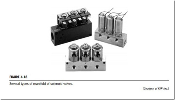
A manifold of solenoid valves consists of a matrix of solenoid valves mounted in modules on a skid with adjustable legs along one direction (Figure 4.18). The number of valves depends on the elements to be connected and on the functions of each of these elements. A plurality of solenoid valves is arranged and placed on the installation face of the manifold, and a board formed with an electric circuit for feeding these solenoid valves (Figure 4.18). Each solenoid valve includes a valve portion con- taining a valve member and a solenoid operating portion for driving the valve member. The board is mounted on the first side face of the manifold under the solenoid operating portion. The board can be attached and detached while leaving the solenoid valves mounted on the manifold, feeding connectors and indicating lights being provided in positions on the board corresponding to the respective solenoid valves. Each feeding connector is disposed in such a position that it is connected to a receiving terminal of the solenoid valve in a plug-in manner when mounting the solenoid valve on the manifold. Each indicating light is disposed in such a position that it can be visually recognized from above the solenoid valve while leaving the solenoid valve mounted on the manifold.
This manifold allows the centralizing of the functions of one or various tanks in a modular way, enhancing the efficiency of the system and the degree of control over the process. The solenoid valve manifold is an automated alternative to flexible hoses and flow divert panels with changeover bends. As many valves as the number of functions the element has to perform are connected to the tank or working line. No manual operation is required. The operation is automated, preventing any risk of accidents.
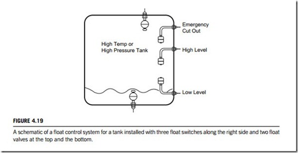
Float control systems that monitor liquid or powder levels in containers such as tanks and reservoirs have two kinds of sensors; float switches and float valves. In a float control system, float switches are used to detect liquid or powder levels, or interfaces between liquids; float valves control the liquid or powder level in elevated tanks, standpipes, or storage reservoirs and modulate the reservoir flow to maintain a constant level.
Figure 4.19 is a float control system monitoring the liquid level of a high-temperature or high-pressure tank using both float switches and float valves. Three switches are located along the right side of this tank to detect three different levels of liquid by turning on either alarms or signals once the liquid reaches them. The two valves set at the top and bottom of this tank are used to input or output the liquid and maintain the appropriate levels in this tank.
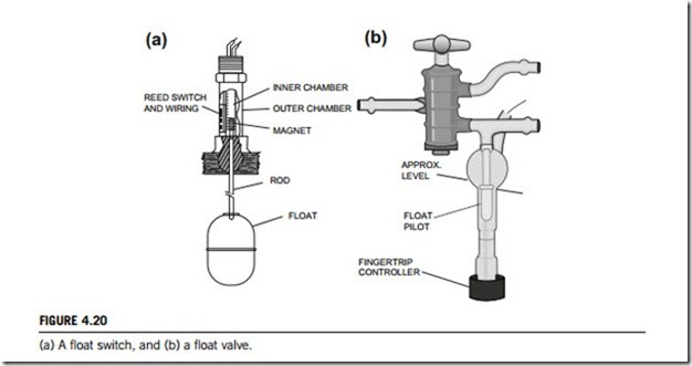
Float control systems require both float switches and float valves to work. Figure 4.20(a) is a diagram of a sample float switch, and Figure 4.20(b) is a diagram of a sample float valve.
(1) Float switch
Float switches (Figure 4.20(a)) can be used either as alarm devices or as control switches, turning something on or off, such as a pump, or sending a signal to a valve actuator. What makes level switches special is that they have a switched output, and can be either electromechanical or solid state, either normally open or normally closed.
Float switches provide industrial control for motors that pump liquids from a sump or into a tank. For tank operation, a float operator assembly is attached to the float switch by a rod, chain, or cable. The float switch is actuated on the basis of the location of the float in the liquid. The float switch contacts are open when the float forces the operating lever to the up position. As the liquid level falls, the float and operating lever move downward. The contacts can directly activate a motor, or provide
input for a logic system that can fill the tank. As the liquid level rises, the float and operating lever move upward. When the float reaches a preset high level, the float switch contacts open, deactivating the circuit and stopping the motor. Sump operation is exactly the opposite of tank operation.
(2) Float valve
A float valve (Figure 4.20(b)) is mounted on the tank or reservoir inlet, below or above the requested water level. The float pilot can either be assembled on the main valve (for above-level installation) or be connected to the main valve by a command tube. The valve closes when the water level rises, by filter discharge pressure acting with the tension spring on the top of the diaphragm in the valve cover chamber, thus raising the float to its closed position. It opens when the float descends, due to a drop in water level by filter discharge pressure acting under the valve disk. The difference between maximum and minimum levels is very small and is affected by the length of the float pilot arm. In practice, the water level is maintained continuously at the maximum point as long as the upstream flow exceeds the downstream flow.
Flow valves
Measuring the flow of liquids and gases is a critical need in many industrial processes, such as chemical packaging, wastewater treatments, and aircraft manufacturing. In some industrial operations, the ability to conduct accurate flow measurements is so important that it can make the difference between making a profit and taking a loss. In other cases, a failure in flow control can cause serious (or even disastrous) results. Flow control systems are designed specifically for operation with a wide range of liquids and gases in both safe and hazardous areas, in hygienic, high-temperature, and high-pressure environments, and for use with aggressive media. Some examples of such applications are pump protection, cooling circuit protection, high and low flow rate alarm, and general flow monitoring.
The technologies for gas flow meters and liquid flow meters vary widely. The most common types of operation principles are inferential flow measurement, positive displacement measurement, velocity measurement, true mass flow measurement, and thermodynamic loss measurement. The main types of operating principles for gas flow meters and liquid flow meters are given below.
(1) Gas flow switches and liquid flow switches, velocity
Gas flow switches and liquid flow switches are used to measure the flow or quantity of a moving fluid in terms of velocity. The most common types are inferential flow measurement, positive displacement, velocity meters, and true mass flow meters.
Inferential measurement refers to the indirect measurement of flow by directly measuring another parameter and inferring the flow based on well-known relationships between this parameter and flow. The use of differential pressure as an inferred measurement of a liquid’s rate of flow is the most common type that is in use today.
Positive displacement meters take direct measurements of liquid flows. These devices divide the fluid into specific increments and move it on. The total flow is an accumulation of the measured increments, which can be counted by mechanical or electronic techniques. They are often used for high-viscosity fluids.
Velocity-type gas flow switches and liquid flow switches are devices that operate linearly with respect to volume flow rate. Because there is no square-root relationship, as with differential pressure devices, their range is greater.
(2) Liquid flow switches and gas flow switches, mass
Liquid and gas flow switche are devices used for measuring the flow, or quantity of a moving liquid or gas, respectively, in terms of units of mass per unit time, such as pounds per minute.
These may be sensors with electrical output or may be standalone instruments with local displays and controls. The most common types are true mass flow meters.
True mass flow meters are devices that measure mass rate of flow directly, such as thermal meters or Calorie meters. The most important parameters are the flow range to be measured, and whether liquids or gases will be the measured fluids. Also important are operating pressure, fluid temperature, required accuracy. Typical electrical outputs for mass gas flow meters and liquid flow meters are analog current, voltage, frequency, or switched output. Computer output options can be via serial or parallel interfaces. These sensors can be mounted as either inline or insertion devices. Inline sensors can be held in place by using flanges, threaded connections, or clamps. Insertion style sensors are typically threaded through a pipe wall and stick directly in the process flow.
(3) Gas flow switches and liquid flow switches, volumetric
Gas flow switches provide output based on the measured flow of a moving gas in terms of volume per unit time, such as cubic feet per minute. Liquid flow switches, volumetric, are devices with a switch output used for measuring the flow or quantity of a moving fluid in terms of a unit of volume per unit time, such as liters per minute.
A clear understanding of the requirements of the particular application is needed to select the correct type of switch. With most liquid flow measurement instruments, the flow rate is determined inferentially by measuring the liquid’s velocity or the change in kinetic energy. Velocity depends on the pressure differential that is forcing the liquid through a pipe or conduit. Because the pipe’s cross-sectional area is known and remains constant, the average velocity is an indication of the flow rate. The basic relationship for determining the liquid’s flow rate in such cases is Q ¼ V x A, where Q is the liquid flow through a pipe, V is the average velocity of the flow, and A is the cross-sectional area of the pipe. Other factors affecting liquid flow rate include the liquid’s viscosity and density. Specific applications should be discussed with a volumetric gas flow switch manufacturer before purchasing to ensure proper fit, form, and function.
Both volumetric gas flow switches and volumetric liquid flow switches are available with four different meter types; inferential flow meters, positive displacement meters, velocity meters, and true mass flow meters. The basic operating principle of differential pressure flow meters is that the pressure drop across the meter is proportional to the square of the flow rate, so the flow rate is obtained by measuring the pressure differential calculating its and square root. Direct measurements of liquid flows can be made with positive-displacement flow meters.
(4) Pneumatic relays
Pneumatic relays control output air flow and pressure in response to a pneumatic input signal. They can perform simple functions such as boosting or scaling the output, or complex reversal, biasing, and math function operators.
