VIDEO DISC RECORDING AND PLAYBACK
The enormous popularity of the gramophone record and its playback equipment and the rapid growth of television made it an obvious idea to look at the possibility of recording video signals on a disc. The use of a disc, as an information carrier, has the advantage that one has immediate access to any program part, but of even far greater importance is its low price by using a method of production which could be similar to that of the gramophone disc.
Research on this subject had started in Philips laboratories by 1969. Earlier investigations in the same field were made, but it was only the availability of the laser as a light source with very high brightness and manufactured in an industrial way that offered the possibility of a practical realisation. It was in September, 1972 that the first demonstration for the International trade press was given with a laboratory set-up and using a master disc as the information carrier.
Subsequent demonstrations in Berlin in 1973, Tokyo in 1974 and New York in 1975 proved the feasibility of the system and created great interest. The object of these demonstrations was to prove the superiority of the optical system over the alternative systems and thus promote the creation of one standard.
OPTICAL RECORDING MEDIUMS
The storage of information by optical methods has many advantages over the conventional method of magnetic recording. As optical recording had obviously much to offer, an intense research began for materials on which information could be stored with the aid of a laser. Three classes of materials that seem suitable for the optical recording of information are: tellurium–selenium alloys, organic compounds and magneto-optical materials.
TELLURIUM–SELENIUM ALLOYS
One of the new materials for the storage of information is a polycrystalline tellurium–selenium alloy to which small quantities of other alloys (arsenic, for example) are added to give better control of the melting point and the stability of the material. A thin layer of the alloy is applied to a substrate. A narrow laser beam is used to melt this material locally so that holes are created with the same depth as layer. During the readout process, with a less intense laser beam, the presence or absence of holes produces differences in the reflection of laser light. These differences in reflection represent the information in coded form.
The disc with a tellurium–selenium alloy is ideally suitable for use as a storage medium for both digital data (alpha-numeric information or digital audio) and video recording.
The use of tellurium–selenium alloys also makes it possible to record information on a disc, erase it and then use the disc again to record new information. By choosing the energy output of the laser appropriately (compared with the level necessary for the ‘hole’ disc) the polycrystalline material is melted locally, but no holes are formed. After the laser pulse, the molten areas cool down so quickly that they solidify in a metastable
amorphous phase. These amorphous domains reflect differently from the crystalline surroundings on readout. Erasure takes place when a laser with sufficiently high energy level transforms the amorphous domains in the crystalline phase.
In most applications, the disc can be used and erased many times. In principal, storage of both digital data and video recording is possible because of the high S/N ratio.
ORGANIC COMPOUNDS
Organic dyes exist that absorb a great deal of light and have a high reflectance even when applied in thin layers. These thin layers of organic compounds seem to be a promising alternative to tellurium–selenium alloys. The memory effect is again obtained by melting the material locally with a laser to create small pits. The difference from the tellurium–selenium alloy is that these pits do not normally penetrate through to the substrate. The reflectance varies with the depth of the pit. The difference in reflection created by the pattern of pits is used when the information is being read. The melting process is irreversible, so the disc can only be written once.
It has been found that these organic compounds retain the information just as well as the hole discs with tellurium–selenium alloys. These compounds have also been found to be highly resistant to heat and moisture. Another attractive feature is the simple spin-coating process for applying organic compound to the disc.
This type of disc has many applications. The S/N ratio obtained experimentally is high enough for the storage of both digital and video information.
MAGNETO-OPTICAL MATERIALS
Amorphous magnetic gadolinium–iron–cobalt compounds have been known for a long time. A laser beam can be used to heat the material locally, reverse the polarity of small areas and freeze it in this state. This technique makes it possible to write on a magnetised layer in a pattern of areas of opposite magnetisation directions. This type of pattern can then be read out with polarised laser light. The direction of polarisation of the reflected light is rotated slightly with respect to the polarisation of the original laser beam as a result of the Kerr effect. The written areas on the disc can, therefore, be distinguished from the unwritten areas and information can be read out. The information can be erased just as easily as it is written. The areas to be erased are heated by the laser, while ans external magnetic field is applied with the same direction as the original magnetisation of the layer; the magnetisation of the heated area reverts to its original direction after cooling. The information can be written, erased, and rewritten as often as required.
At present the S/N ratio is only moderate, so this information storage method is suitable for digital data only (alpha-numeric information and digital audio signals). It could very well be possible to improve the S/N ratio sufficiently for recording of video signals.
EVOLUTION OF VIDEO DISC
The concept of a gramophone record that produces pictures first became a reality in the 1920s, long before the development of the first video cassette. John Logie Baird successfully created a mechanical television system by recording simple visual signals on an ordinary 78 r.p.m. gramophone record and in 1935 his invention went on sales in Selfridges. Purchasers of Baird’s video disc were able to view various British public figures in profile. The invention failed to capture the imagination of the public and was eventually withdrawn.
It was 35 years before the first video disc appeared but it was never actually launched on the British market. It was supposed to be marketed by a company called Teldec, jointly by the German company Telefunken and Decca in the U.K. Made of plastic and with a playing time of only ten minutes the disc was named TeD; however due to a mixture of technical problems and disagreement between Teldec partners, it never became commercially available. The Teldec debacle, however, set the video disc ball rolling, prompting a burst of activity from the electronic companies around the world as they attempted to improve upon the original idea.
Philips was the first off the mark unveiling its video disc at a press conference in Eindhoven in 1972. It has taken the company another ten years to introduce the first commercially available video disc and video disc player in the U.K.
In the United States, RCA introduced its Select Vision system, and in Japan, government pressure for technical standardisation finally produced some results with JVC developing its VHD video disc system (VHD is the short form of Video High Density).
The use of disc, as an information carrier, has the advantage that one has immediate access to any program part, but of even greater importance is its low price by using a method of production which could be similar to that of the gramophone disc.
It was only the availability of laser as a light source with very high brightness and manufactured in an industrial way that offered the possibility of a practical realisation.
Subsequent demonstrations in Berlin in 1973, Tokyo in 1974, and New York in 1975 proved the feasibility of the system. The object of the demonstrations was to prove the superiority of the optical system over the alternative systems and thus create the promotion of one standard.
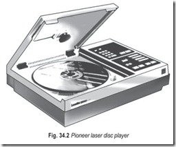
In accordance with this endeavour, an arrangement was reached with Pioneer in 1974 to combine efforts in further developing the system. At the same time there was the numerous advantage of the availability of a wealth of software for the Pioneer and Philips video disc systems, since known as Pioneer Disco-Vision system and Philips VLP system (Video Long Play). The Pioneer and Philips video disc system is much more than just an entertainment, item. It is a new communication system offering the consumer information of his own choice at a time that suits him. Pioneer Laser Disc Player is shown in Fig. 34.2.
The superiority of the system originates from the application of optics for reading out the information on the disc. Due to the absence of a physical contact between the disc and reading out device, no wear occurs. There is an effective protection of information on the disc against finger prints, dust and scratches. In this respect the video disc is superior to the gramophone disc! Finally, the optical system offers a number of playing modes to be utilised that are inconceivable with mechanical systems.
VIDEO DISC
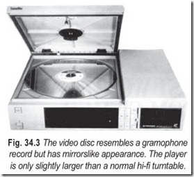
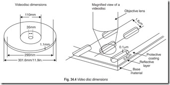
The Pioneer and Philips video disc resembles very much in its physical shape of a gramophone records, Fig. 24.3. It consists of a transparent plastic material with standardised diameters of 30 cm and 20 cm and a thickness of 1.1 mm. The most striking differences with an audio record are its mirror like appearance due to a reflective coating and the fact that it can be played on one side only. The basic difference however, lies in the structure of information. Whereas the audio disc has grooves, the walls of which are modulated with an audio signal, the video disc, in view of the requirements of a much higher information density, has tracks with a much finer information and with a spacing that is about 60 times smaller than that of the audio disc.
Two basic types of disc are available; one rotating at 1800 r.p.m. for areas with NTSC television system and another rotating at 1500 r.p.m. for areas with PAL or SECAM television system. For obvious reasons, the two types are not interchangeable.
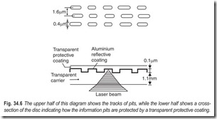
The information on the disc exists as a spiral track starting at the inside of a fixed diameter and moving to the outside. Average track pitch is 1.6 µm, resulting in a playing time of approximately 30 minutes for a 30 cm diameter disc. The information in the track consists of small depressions called pits with variable distance and length. Pit width is 0.4 µm, where as pit depth is approximately 0.1 µm. Instead of depressions, other elements suitable for absorption or dispersion of light can also be used and do exist mainly as a result of the mastering system used.
The total track length on a 34 cm disc is about 34 km and the linear speed of tracking varies from 37 km/h at the innermost track to 100 km/h at the outermost track. One complete television picture (two fields) requires a surface area on the disc of 0.5 mm at the innermost track.
VIDEO DISC MASTERING AND REPLICATION
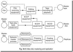
The production process of a video disc is more or less comparable with that used for conventional gramophone record. First a master recording is made. It consists of a glass plate with a photosensitive layer deposited on one side. The coded signal of the information to be stored modulates the beam of a 1 mm laser which writes the information in the surface of the disc. Cutting is done on real time basis; that is it requires only as much as the program lasts and recording takes place at the disc’s rotational speed of 30 r.p.s. for (revolutions persecond) NTSC and 25 r.p.s. respectively for PAL and SECAM. In principle, every normal type of TV signal source can be connected to the cutting device. In practice however, 50 mm magnetic recording tape is used as a program carrier.
Exposure to the laser beam is followed by a development process which leaves a pattern of pits on the master from which, via a galvanic process, stampers are made which are used for disc production in a way similar to processing of gramophone records.
After processing, an extremely thin metal coating, not more that 0.04 µm thick is deposited on the information side which is then sealed with a protective layer, as shown in Fig. 34.6.
VIDEO DISC FORMATS
The three non-interchangeable video disc formats fall into two basic categories; optical and capacitance. The laser optical system (also called VLP) which is employed by Philips, uses a laser beam to recover the electronically encoded information stored on the disc. The capacitance system (also called capacitance electronic disc or CED), employed by both JVC and RCA, uses a stylus and tracking arm similar to that of a conventional record player to recover the information recorded on the grooves of the disc. There are two variations of the laser optical system reflective and transmissive. There are also two variations of the capacitance system, the video/audio high density system (VHD) and the capacitance electronic disc system (CED).
LASER VISION
The core of the Philips laser vision are the shiny silver video discs which hold the pre-recorded program material. These are optically read by a high precision laser, built into the laservision player. The laservision system features a level of picture and sound without a parallel in video. Flawless picture reproduction, full of rich colours, is accompanied by high stereo sound when the player is connected to a stereo TV or hi-fi audio system.
There are two types of Laservision discs.
Long play discs for straight forward uninterrupted playback of entertainment programs and active play discs which involve the viewer in learning a new skill or subject and making full use of the player’s many and versatile picture search facilities that help you to quickly locate any point on the disc and study parts in detail.
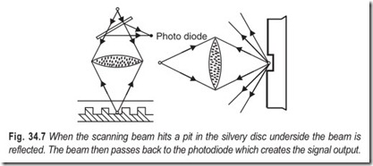
The information etched on the reflective material of the disc in a series of pits is read off with a fine beam created by a helium–neon laser. By means of a series of lenses, gratings, prisms and mirrors, the laser beam is directed to the disc underside where it is moved by a scanning lens. When it hits a pit in the silvery surface, Fig. 34.7, the beam is reflected. The reflected beam then passes back to the photodiode which creates the signal output.
In a similar system, which is worked in France by Thomson CSF, the laser beam is not reflected from the surface of the disc, but is actually transmitted through it. Variations in the quality of the beam, created by the information etched on the disc, are then used to construct the electrical signals need to create a TV picture.
Any Laservision disc may be freely handled, cleaned and replayed as often as you wish. The program material is held in billions of tiny pits punched into the disc’s surface and then covered by a transparent material which protects it against dust scratches and finger marks. Because the disc is scanned by a laser light beam, its life is virtually infinite. Laservision discs are marketed by a steadily increasing number of leading program distributors under their own labels.
SELECTAVISION (RCA)
The cheapest and the most basic of the three video disc formats, with the current models offering only mono sound and picture search, selectavision discs, based on the capacitance system, have a maximum running time of one hour per side.
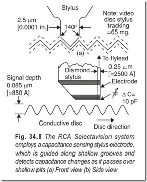
The RCA stylus recovers information from the disc surface by direct electrical means. The selectavision disc is either formed from or coated with electrically conductive material and the stylus serves as a conductive electrode. Although the groove appears to be smooth, it does have tiny pits along the bottom which produce changes in electrical capacitance between the disc surface and the stylus electrode. These changes in capacitance are sensed by a tuned circuit to produce an output of video signals.
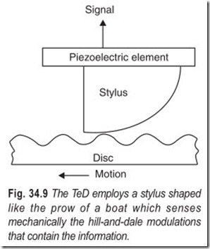
The TeD and RCA systems, rely on a stylus following a minute surface groove and fail to function if the disc surface is damaged. For this reason, the floppy TeD disc is always stored in a sleeve which is itself loaded into the player for automatic extraction of the vital foil, the sleeve remaining inside the player until the disc has played. RCA discs, which must also be warp free and are rendered useless by finger marks, which confuse the capacitance effect, are stored in a caddy from which the player automatically extracts the disc for playing.
VIDEO HIGH DENSITY (JVC/THORN-EMJ)
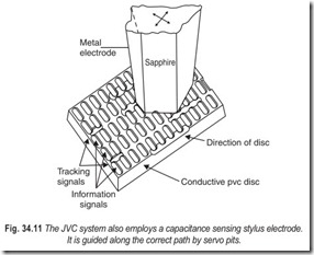
Technically and price wise, VHD falls between laservision and selectavision. The JVC system resembles the RCA approach in its use of capacitance pick-up from an electrically conductive disc with a spiral of pits on its surface. But the 25cm (10 inch) JVC disc has a smooth surface with no groove. The stylus electrode is constrained to follow the spiral pits by a servo system. The spiral of program pits (which the electrode stylus tracks to produce pictures on TV screen) is interlaced with a spiral of tracking pits which are sensed to control the servo system to guide the electrode.
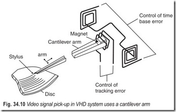
Fig. 34.10 illustrates the method of controlling the stylus. The stylus is mounted at the end of a cantilever pick-up arm opposite that end on which a magnet is attached. Fixed coils are positioned near the magnet: a single coil is wound around but not in contact with the magnet, and a pair of vertical coils are positioned, one each on either side of the coil, and in phase opposition to each other. Thus the stylus can move transversely and longitudinally in response to the particular current flowing in these coils. The current is varied by a tracking error signal, or by a command to move the stylus to a desired track, permitting various functions during playback.
The JVC disc rotates at twice the speed of the RCA disc, and gives a playing time of one hour each side. It can also provide instant replay of selected short passages. Freeze frame is possible but not easy, for example, it requires a memory to store one of the two frames recorded for each revolution of the disc.
Because there are no grooves and no tracking stylus to follow them, the JVC electrode is required only to slide over a smooth disc surface and will doubtless have a longer life than any other system employing a stylus in groove. However, no one yet knows how long a disc will last, especially when used to display still frames. With any contact system there is inevitably some abrasion.
Although the JVC system is relatively simple to construct, it requires complex servo control system
which may put the price higher than the mechanically very simple RCA system.
VIDEO DISC SYSTEMS — A COMPARISON
Common to all video disc systems is the process in which a program (originally recorded on magnetic tape) is recorded on to a master metal disc. The metal master is then used to mass produce plastic discs which are played on the video dics player (VDP).
Plastic discs for the laser video (LV) optical pick-up system are coated with metal on one side (the recorded surface) and then bonded with the metal inside for protection. Carbon is added to discs for the two capacitive pick-up systems. CED and VHD, to make the disc conductive. A lubricant for smoothing the pick- up and reducing wear is added to the CED discs. This lubricant is necessary because the CED system has grooves on the disc for stylus tracking. This makes the CED system simpler (no servo tracking is required) but does produce some wear. However, the wear on a CED disc in no way compares with the wear of a conventional audio record. RCA demonstrated this by playing a single groove of a CED disc 9000 times without noticeable deterioration in the video display.
The three video disc systems also have similarities. All three systems use a plastic disc rotating on a turntable. In all the systems, the player picks up information represented by changes in the disc surface and converts the information into signals for playback on a television set. All systems use frequency modulation (FM) for both video and audio signals. Each disk has a spiral track to carry the information rather than a series of circular tracks.
In spite of all the basic similarities, the systems differ not only in the pick-up technique (optical versus capacitive) but also in the format in which the information is encoded and in the method by which information is tracked. Other differences include size, material, rotation speed and signal-protection schemes.
RECORDING SYSTEM
In the optical video disc there is a single information track in which all the information is stored for the reproduction of a colour television program with two sound channels and data signals.
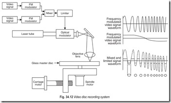
The nonlinearity of the master recording process limits the choice of possible encoding techniques and a two-level signal recording was found to be the most attractive solution. On this track the information is enclosed in the length and the spacing of the pits or, in other words, for a rotating disc in the repitition frequency, determined by the average length of the pits, and a pulse width modulation of the frequency, determined by the modulation of the length of the pits, Fig. 34.12.
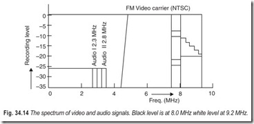
The composite video signal employed in the video disc system is frequency modulated on a carrier at 8 sMHz which is pulse width modulated by two hi-fi audio channels at 2.3 MHz and 2.8 MHz.
Fig. 34.13 shows the block diagram of the signal processing for coding the video and audio system. Before FM modulation of the video signal pre-emphasis time constants of 50 µs and 12.5 µs are employed. The audio signals are FM modulated on carriers of 2.3 MHz and 2.8 MHz with a frequency deviation of
+ 100 kHz and a pre-emphasis of 75 µs. The two audio carriers are summed with the FM carrier and after limiting, the output signal is used to modulate the intensity of a laser beam passing through an electro- optical modulator in the master recording machine.
The spectrum of video and audio signals is given in Fig. 34.14. The master is used as a starting point for the production of discs.
PLAYBACK SYSTEM
In reading back the information, the reflected light returning from the disc falls on a photodiode and its output is amplified and corrected according to the frequency characteristic of the player. A high-pass filter separates the video information and the filters have a crossover frequency at 3.5 MHz. The separated FM signals are then demodulated and a de-emphasis is applied to compensate for the pre-emphasis employed before recording, in order to achieve a better S/N ratio and a more uniform frequency response. The playback system is shown in Fig. 34.15.
DIGITAL ADDRESS SIGNALS
As part from video and audio information, the disc contains a number of signals, inserted in the non-visible lines of the blanking periods. These are in the first place Vertical Interval Reference (VIR) and Vertical Interval Test (VIT) signals for testing purposes (lines 19,20,282,283) and secondly a number of digital address signals for various purposes (lines 17, 18, 280, 281).
The address signals have the following functions:
A. Lead-in tracks (min 600 tracks = 20 seconds)
Start code: The “read” objective is sent with normal speed forward to the program area on the disc. The “start” code is present in all fields of the lead-in tracks.
B. Program area :
1. Picture Code : Consists of a picture number and a key for either continuous play in the normal forward mode or a stop key for automatic stopping in the “freeze frame” mode.
2. Chapter Code : Consists of a chapter number and a key for either continuous search during depression of the search button or a stop key for automatic stopping of the search action. The chapter code is optional, depending on the type of program, and may be present only in the program area in those fields without a picture code.
C. End tracks (min 600 tracks)
End Code : The read objective is sent back to the beginning with a speed 100 × normal speed. The end code is present in all fields of the end tracks.
SOLID-STATE LASER
When Philips originally invented its video disc system, the laser the company planned to use was an older, bulky type (Fig. 34.16) which was both expensive and difficult to manufacture and align.
As Philips went further down the track and invented the compact disc (CD) player, it became obvious that what was required was a cheap, easily produced, robust laser system; in other words, a solid-state laser.
The first commercially viable, and commercially available solid-state laser came from Matsushita, Japan’s largest electronics concern, MEL 4745 laser. It was developed by the specialist semiconductor division of Matsushita, Matsushita Electronics Corporation. It is shown in Fig. 34.17.
In order for a semiconductor laser to be ideal for use in optical information processing systems, the following factors are essential:
1. Low threshold current
2. High power-output
3. Stable single transverse mode oscillation
4. Circular radiation pattern of laser beam
5. Long life
Conventional semiconductor lasers, however, could not satisfy all of these conditions. Matsushita succeeded in satisfying all of the above key factors by adopting a unique terraced substrate (TS) construction.
The TS laser can confine laser beams in a far narrower wave guide—resulting in higher power output with lower threshold current.
In the fabrication of TS lasers, the face of the n-GaAs substrate is terraced by chemical etching, on which a double heterostructure is formed by successively growing an n-GaAlAs cladding layer, a GaAlAs active layer, a p-GaAlAs cladding layer and an n-GaAlAs isolation layer.
The active layer is grown thick at the terraced part, forming a modified rib—waveguide structure. Such a structure is very effective for confinement of a laser beam and for a stable single transverse mode oscillation. The TS structure also improves the concentration of injection current in the active region resulting in a remarkable decrease in non-effective current. The ratio of the effective current flowing through the terraced active region to the total injection current is in excess of 80 per cent.
Through these improvements, the threshold current has been reduced to a level of lower than 30 per cent of conventional lasers while still keeping a high power output.
The TS laser MEL 4745 has a built-in PIN photodiode and can be easily connected with an APC circuit to keep the light output constant.
FOCUSING
A thick video disc with a thickness of 1.1 mm rotating in free air at 30 Hz is generally stable but not critically damped. In order to restrict the action of transverse waves in the frequency range 0–15 Hz and also to compensate for the “umbrella” form deflection of the disc under its own weight, a stablisation system has been incorporated. Stabilisation is achieved in the player by means of an air bearing, which is created by the centrifugal action of the rotating disc on the surrounding air.
A plate with a central hole is positioned in the vicinity of the rotating disc’s surface. This creates an air bearing having both the desired damping and stiffness characteristic. Disc stabilisation obtained in this way is by no means sufficient to guarantee the required accuracy on the distance between the disc and read objective.
In order to read the microscopically small information details on the disc, an objective lens with a large numerical aperture is required, which thus has a small depth of focus. Numerical aperture (N.A) is defined as the product of the refraction index and the sine of the angle between the optical axis and the outermost light ray contributing to the imaging (Fig. 34.18).
With N.A = 0.4, a maximum out-of-focus allowed is 2 µm. In view of tolerances in the disc and player construction this accuracy can only be realised by means of a servo control system including a moving read objective that can follow the undulations of the disc.
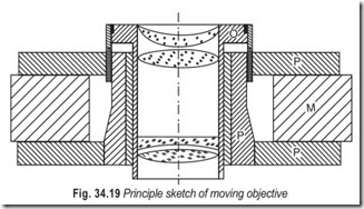
As can be seen in Fig. 34.19 the objective lens is mounted in a system similar to that of a loudspeaker voice coil and thus operates according to the electrodynamic principle. Depending on the direction and magnitude of current through the coil it executes controlled vertical movements in order to follow the irregularities.
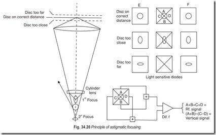
To understand the way in which the control signal is obtained, it is necessary first to have a closer look at the photodiode which detects the light beam reflected by the disc. In fact this diode consists of two segments E and F and a third one between the two which is composed of four quadrants A, B C and D (Fig. 34.20). The light beam focused on the central segment will normally create a circular spot and thus all four segments will receive an equal amount of light. The sum of the electrical signals over these four quadrants is the RF signal or video-information.
However, on its way to the diode the reflected beam passes a cylindrical (astigmatic) lens. As a result, the light spot on the diode which normally has a circular shape obtains an elliptical deformation if the information plane in the disc changes its distance from the objective. If this occurs each quadrant no longer receives an equal amount of light and so a difference signal can be derived. This difference signal, once it has been amplified and processed, can be used to change the position of the objective lens with respect to the disc.
The largest vertical movements of the disc occur at the speed of rotation and decrease rapidly at higher frequencies, Disc specification sets the maximum value at 10 g but the player can cope with accelerations as high as 14 g and still remain below an out-of-focus value of 2 µm.
RADIAL AND TANGENTIAL TRACKING
The information on the disc is contained in a spiral that is read from the inside to the outside. For this purpose the ‘read’ objective and other optical elements are mounted on a sledge driven by a small dc motor, and moving radially under the disc. With an average track pitch of 1.6 µm and the disc rotating at 1800 r.p.m. this means an average linear speed of the sledge of 3 mm/m.
The scanning light beam has to remain focused on the track with a radial accuracy of 0.1 µm, a requirement that cannot be met by a purely mechanical guidance system. By varying the speed of the drive motor by incorporating it in a servo control system certain slow corrections are possible. However, to cope with the effects caused by eccentricity of the spinning disc, for example, certain additional measures are required and use is made of pivoting mirror by means of which the light spot can move radially over the disc.
This mirror is mounted in an assembly resembling a moving coil ammeter where the coil is part of the radial servo control circuit.
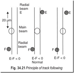
The information on the track can only be read optically and the deviation can also only be measured optically. For this purpose two auxiliary beams of light are used which are slightly displaced from the centre-line of the track, in opposite directions, so that they are partly on and partly off the track as shown in Fig. 34.21.
After deflection from the disc the two auxiliary beams each fall on its own photodiode E and F in Fig. 34.21 and the average current through the diodes depends on the auxiliary beam relative to the track.In fact the difference signal of the two diodes after amplification passes a low-pass filter with a cut off frequency of 20 kHz and is then used as an error signal in the control system. If the average position of the mirror deviates from its zero position, the average current is used to control the slide mirror for correction of the position of the sledge.
BLOCK DIAGRAM OF VLP PLAYER
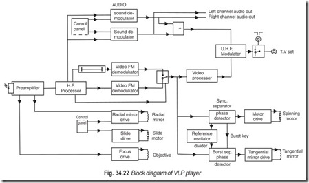
From the discussion so far, the larger part of the block diagram will be self-explanatory. A few items, however, require an explanation.
In the event of a dropout (an interruption of the signal due to any imperfection in the disc) a drop-out detector operates as a switch by means of which a parallel channel, fitted with a line scan delay, can provide information of the previous line. Of the two available audio channels, either one of the two or both (in the case of stereo), can be connected to the VHF modulator. Since normal television receivers are monophonic, the two demodulated audio signals are available at output sockets at the back of the VLP player. These can be connected to a stereo amplifier.
VLP PLAYER CONTROLS
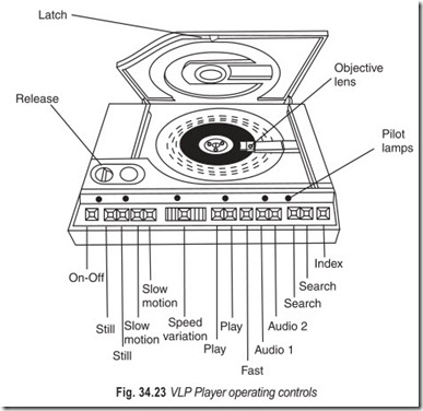
The player Fig. 34.23, is housed in a plastic case of modern design. All operating controls but one are arranged on a sloping panel at the front, together with a number of LEDs indicating which function has been switched on.
Measures have been taken to prevent opening the lid when the disc is spinning and or the laser is ON. In order to satisfy the most stringent safety requirements a double protection against laser radiation is provided for when the lid is open. Not only is the laser supply switched OFF automatically, but also a small metal shield is placed in the light path. Below the lid and fixed to it is the stablisation disc and a magnetic device for clamping the video disc on its turntable. The Pioneer system uses a spring clamp to secure the disc.
The spinning motor is a standard dc cordless direct-drive rotor type.
The electronic circuit is divided into functional units of the same type as used in Philips colour TV sets. They can be plugged in and out easily, thus simplifying fault finding and repair. All optical components, the laser with its ignition unit, the sledge drive mechanism and the preamplifier are situated on the sledge.
In order to take advantage of the versatility of the system, the VLP player has been equipped with a number of operating controls for a variety of functions. Apart from the latch for releasing the lid, all other controls are of the push button type and arranged in a logical sequence.
On the palyer we find the following functions:
Mains switch : ON/OFF
Freeze Frame : Two push buttons in order to obtain a still picture. Repeated depressing
of the button still forward produces next picture. Repeated depressing of the button still reverse gives the preceding picture.
Slow motion : Separate push buttons for forward and reverse action in combination
with a sliding potentiometer vary the speed between 30 frames (normal speed) and 4 seconds per picture.
Normal speed : Separate push buttons for forward and reverse at normal speed.
Fast forward : Forward motion at a speed three times normal. Fast forward action is
obtained only while keeping the button depressed. After release the apparatus is in the still picture mode.
Sound : The player has two separate sound channels, each of which can be switched ON or OFF. This not only gives the player stereo capability, it also means that dual-language discs could be used. Using this feature, the sound would, of course, be mono.
Search : Separate push buttons for forward and reverse search through the program with a 100 × normal speed. This means that it takes 18 seconds from start to end of the a 30 cm diameter disc. The search action takes place while keeping the button depressed. Release of the button brings back the apparatus in the playing mode it had before activating search.
Index : Picture number and chapter number can be made to appear on the screen by pressing the “index” button. When the button is pressed once the chapter number appears, when it is pressed again the picture number appears, and when it is pressed a third time the picture number disappears.
AUTOMATIC ACTIONS
A great many automatic functions have been incorporated in the VLP player both to ensure a flawless performance of the apparatus under all circumstances and in order to make it foolproof. A number of other automatic functions are particularly intended for making it user friendly. These are :
Priority mode : After switching ON the apparatus will always be in the normal play forward mode with both sound channels connected.
Program end : At the end of a disc the ‘read’ objective will automatically move with ‘search speed’ to the beginning of the disc. The same will happen after interruption of the playing of a disc by releasing the lid.
Program Start : If the ‘read’ objective lens arrives at the beginning of a disc and the lid is closed, the player will start again in the normal ‘play forward’ mode.
Stop during normal play : If an appropriate picture code is on the disc the player stops immediately at that picture and remains in the ‘freeze frame’ position.
Stop during search : If an appropriate chapter code is on the disc, the player stops the search action at the beginning of a chapter. Search is resumed after releasing and subsequent depressing of the ‘search’ button.
OPTICAL MEMORY DISCS
Magnetic discs are based on ideas which were current 30 years ago in the recording industry. With a normal record you start playing on the outside run and the track goes round and round in a spiral to the centre. One problem with the cassettes is that you have to record all the information in a serial form. So if you have recorded say 8 programs, and want the information stored in the last one, you have got to start all the way from the beginning until you get to the information you want. One way of overcoming this setback is to take a normal LP-type record approach, where although you have got serial recording format, you have designated points called tracks. As there is a certain amount of random access, it is possible to ‘drop in’ at any point.
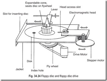
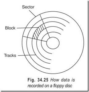
A magnetic disc, Fig. 34.24, is divided up into discrete tracks in the same way as a normal LP record. But instead of the tracks being in a spiral they are all concentric. A small magnetic recording head, just like a recording head on a small cassette recorder, is then moved from say track 0 to, say, track 35 (Fig. 34.25). The disc unit is instructed that the computer wants to record the next chunk of information on track 5, and it moves the head to track 5 and dumps the information in a similar way to how the information was recorded on a cassette tape, i.e. by modulating the 1’s and 0’s pulses with a frequency that can be recorded magnetically.
A few years ago IBM came along with the floppy disc, which is now being made in a whole series of difference formats, 8”, 5.25” and now 3.5” in diameter. If a sheet of plastic covered with a thin layer of magnetic material is spun at 300 r.p.m. it keeps relatively rigid.
The disc is split into a series of tracks, which vary from about 35 to 80. Each track is itself split into a number of sectors.
The number of sectors vary, but it is usually about 16. In other words the disc is made of a series of blocks. So to store information it must be possible to keep track of which block or group of blocks the information is stored. One of these tracks is designated the index track, and on that track you store an index of what information is on the disc and where it is. It’s like looking up something in a book; there is an index which tells the recording head exactly where all the information is stored and usually how much information is there.
There are many more sophisticated methods where you might have various check digits or other information stored on the index tracks.
Anyone who has used disc drives will have heard it whirring away making clunking noises. This is the head trying to find the appropriate track. The size of each block can vary from between 256 bytes to 1024 bytes. Unlikes a cassette recorder the information can be spread all over the place.
EXERCISES
Descriptive Questions
1. Compare a video disc with a gramophone record.
2. What are the similarities between the three video disc formats?
3. Briefly explain the different optical recording mediums.
4. With the help of a suitable sketch explain the construction of a video disc along with the dimensions of
(a) diameter (b) track pitch
(c) pit width (d) pit depth
(e) thickness (f) protection layer
5. Briefly explain the recording and playback system of an optical video disc.
6. Describe the digital address signals.
7. Explain the working of a TS laser.
8. What is the significance of radial tracking?
9. What are the different controls on a VLP player?
10. What is the difference between a video disc and an optical memory disc?
11. How data is recorded on a floppy disc?
12. Explain the following :
(a) serial form (b) discrete tracks
(c) blocks (d) index tracks
Multiple Choice Questions
1. The three video disc formats are
(a) interchangeable (b) non-interchangeable
2. With the video disc as information carrier one
(a) does not have immediate access to any program part
(b) has immediate access to any program part
3. The information on the video disc exists as a
(a) spiral track starting from outside (b) groove starting from inside
(c) spiral track starting from inside (d) groove starting from outside
4. There are two types of laservision discs
(a) standard play (b) long play
(c) esxtended play (d) active play
5. The RCA stylus recovers information from the disc surface by
(a) indirect electrical means (b) direct electrical means
6. The TeD and RCA systems
(a) function even if the disc surface is damaged
(b) fail to function if the disc surface is damaged
7. In response to a tracking error signal the stylus in a VHD system can move
(a) longitudinally (b) transversely
(c) longitudinally and transversely
8. With a single information track, the information is encoded in
(a) the length of the pits (b) the spacing of the pits
(c) the length and spacing of the pits
9. The old bulky lasers were
(a) expensive (b) difficult to manufacture
(c) difficult to align (d) all of the above
10. The TS laser has
(a) higher power output with lower threshold current
(b) lower power output with higher threshold current
Fill in the Blanks
1. The superiority of the Laser Disc Player originates from the application of …………………. for reading out the information on the disc.
2. There is an effective…………………. of information on the disc against finger prints, dust and scratches.
3. Average track pitch is…………………. .
4. Pit width is…………………. whereas pit depth is …………………. .
5. In practice, however,…………………. magnetic recording tape is used as a …………………. carrier.
6. The laser optical system is also called…………………. .
7. There are two variations of the laser optical system,…………………. and …………………. .
8. Long play discs are for straight forward…………………. playback of entertainment program.
9. Active play discs involve the viewer in learning a new …………………. .
10. …………………. is the cheapest and the most basic of the three video disc formats.
ANSWERS
Multiple Choice Questions
|
1. (b) |
2. (b) |
3. (c) |
4. (b) |
5. (a) |
6. (b) |
|
7. (c) |
8. (c) |
9. (a) & (c) |
10. (a) |
Fill in the Blank
|
1. optics |
2. protection |
3. 1.6 µm |
|
4. 0.4 µm, 0.1 µm |
5. 50 mm, program |
6. Philips VLP system |
|
7. reflective, transmissive |
8. uninterrupted |
9. skill |
|
10. Selectavision(RCA) |

