Once conversion from analogue signals into the digital domain has taken place, audio becomes data and a digital audio recorder is no more than a data recorder adapted to record samples from convertors. Provided that the original samples are reproduced with their numerical value unchanged and with their original time base, a digital recorder causes no loss of information at all. The only loss of information is due to the conversion processes unless there is a design fault or the equipment needs maintenance. In this chapter John Watkinson explains the various techniques needed to record audio data.
Types of Media
There is considerably more freedom of choice of digital media than was the case for analogue signals, and digital media take advantage of the research expended in computer recording.
Digital media do not need to be linear, nor do they need to be noise-free or continuous. All they need to do is allow the player to be able to distinguish some replay event, such as the generation of a pulse, from the lack of such an event with reasonable rather than perfect reliability. In a magnetic medium, the event will be a flux change from one direction of magnetization to another. In an optical medium, the event must cause the pickup to perceive a change in the intensity of the light falling on the sensor. In CD, the contrast is obtained by interference. In some discs it will be through selective absorption of light by dyes. In magneto-optical discs the recording itself is magnetic, but it is made and read using light.
Magnetic Recording
Magnetic recording relies on the hysteresis of certain magnetic materials. After an applied magnetic field is removed, the material remains magnetized in the same direction.
By definition the process is nonlinear, and analogue magnetic recorders have to use bias to linearize it. Digital recorders are not concerned with the nonlinearity, and HF bias is unnecessary.
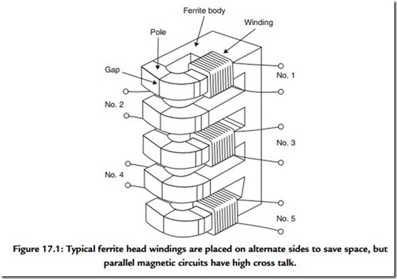
Figure 17.1 shows the construction of a typical digital record head, which is just like an analogue record head. A magnetic circuit carries a coil through which the record current passes and generates flux. A nonmagnetic gap forces the flux to leave the magnetic circuit of the head and penetrate the medium. The current through the head must be set to suit the coercivity of the tape and is arranged to almost saturate the track. The amplitude of the current is constant, and recording is performed by reversing the direction of the current with respect to time. As the track passes the head, this is converted to the reversal of the magnetic field left on the tape with respect to distance. The recording is actually made just after the trailing pole of the record head where the flux strength from the gap is falling. The width of the gap is generally made quite large to ensure that the full thickness
of the magnetic coating is recorded, although this cannot be done if the same head is intended to replay.
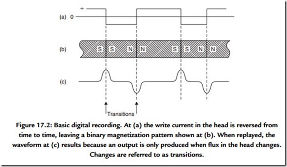
Figure 17.2 shows what happens when a conventional inductive head, that is, one having a normal winding, is used to replay the track made by reversing the record current.
The head output is proportional to the rate of change of flux and so only occurs at flux reversals. The polarity of the resultant pulses alternates as the flux changes and changes back. A circuit is necessary which locates the peaks of the pulses and outputs a signal corresponding to the original record current waveform.
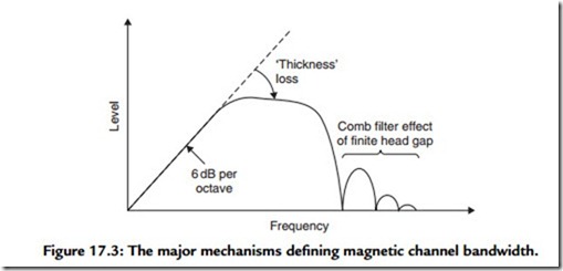
The head shown in Figure 17.2 has the frequency response shown in Figure 17.3. At DC there is no change of flux and no output. As a result, inductive heads are at a disadvantage at very low speeds. The output rises with frequency until the rise is halted by the onset
of thickness loss. As the frequency rises, the recorded wavelength falls and flux from the shorter magnetic patterns cannot be picked up so far away. At some point, the wavelength becomes so short that flux from the back of the tape coating cannot reach the head and a decreasing thickness of tape contributes to the replay signal. In digital recorders using short wavelengths to obtain high density, there is no point in using thick coatings. As
wavelength further reduces, the familiar gap loss occurs, where the head gap is too big to resolve detail on the track.
As can be seen, the frequency response is far from ideal, and steps must be taken to ensure that recorded data waveforms do not contain frequencies which suffer excessive losses.
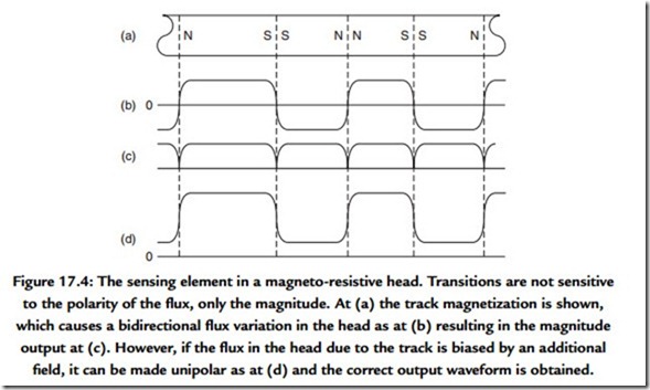
A more recent development is the magneto-resistive (MR) head. This is a head that measures the flux on the tape rather than using it to generate a signal directly. Flux measurement works down to DC and so offers advantages at low tape speeds.
Unfortunately, flux measuring heads are not polarity conscious and if used directly they sense positive and negative flux equally, as shown in Figure 17.4. This is overcome by using a small extra winding carrying a constant current. This creates a steady bias field, which adds to the flux from the tape. The flux seen by the head now changes between two levels and a better output waveform results.
Recorders that have low head-to-medium speed, such as digital compact cassette (DCC) use MR heads, whereas recorders with high speeds, such as digital audio stationary head (DASH), rotary head digital audio tape (RDAT), and magnetic disc drives, use inductive heads.
Heads designed for use with tape work in actual contact with the magnetic coating. The tape is tensioned to pull it against the head. There will be a wear mechanism and need for periodic cleaning.
In the hard disc, the rotational speed is high in order to reduce access time, and the drive must be capable of staying on line for extended periods. In this case the heads do not
contact the disc surface, but are supported on a boundary layer of air. The presence of the air film causes spacing loss, which restricts the wavelengths at which the head can replay. This is the penalty of rapid access.
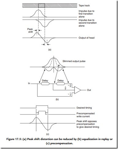
Digital audio recorders must operate at high density in order to offer a reasonable playing time. This implies that the shortest possible wavelengths will be used. Figure 17.5 shows that when two flux changes, or transitions, are recorded close together, they affect each other on replay. The amplitude of the composite signal is reduced, and the position of the peaks is pushed outward. This is known as intersymbol interference, or peak-shift distortion, and occurs in all magnetic media.
The effect is primarily due to high frequency loss and it can be reduced by equalization on replay, as is done in most tapes, or by precompensation on record, as is done in hard discs.
Optical Discs
Optical recorders have the advantage that light can be focused at a distance whereas magnetism cannot. This means that there need be no physical contact between the pickup and the medium and no wear mechanism.
In the same way that the recorded wavelength of a magnetic recording is limited by the gap in the replay head, the density of optical recording is limited by the size of light spot which can be focused on the medium. This is controlled by the wavelength of the light used and by the aperture of the lens. When the light spot is as small as these limits allow, it is said to be diffraction limited. The recorded details on the disc are minute, and could easily be obscured by dust particles. In practice the information layer needs to be protected by a thick transparent coating. Light enters the coating well out of focus over a large area so that it can pass around dust particles, and comes to a focus within the thickness of the coating. Although the number of bits per unit area is high in optical recorders, the number of bits per unit volume is not as high as that of tape because of the thickness of the coating.
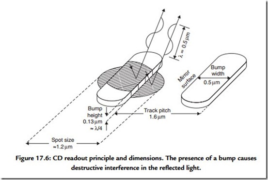
Figure 17.6 shows the principle of readout of the compact disc which is a read-only disc manufactured by pressing. The track consists of raised bumps separated by flat areas. The entire surface of the disc is metalized, and the bumps are one quarter of a wavelength
a phase reversal between the two components of the reflection. This causes destructive interference, and light cannot return to the pickup. It must reflect at angles which are outside the aperture of the lens and be lost. Conversely, when light falls on the flat surface between bumps, the majority of it is reflected back to the pickup. The pickup thus sees a disc apparently having alternately good or poor reflectivity.
Some discs can be recorded once, but not subsequently erased or rerecorded. These are known as WORM (write once read mostly) discs. One type of WORM disc uses a thin metal layer that has holes punched in it on recording by heat from a laser. Others rely on the heat raising blisters in a thin metallic layer by decomposing the plastic material beneath. Yet another alternative is a layer of photo-chemical dye that darkens when struck by the high powered recording beam. Whatever the recording principle, light from the pickup
is reflected more or less, or absorbed more or less, so that the pickup once more senses a change in reflectivity. Certain WORM discs can be read by conventional CD players and are thus called recordable CDs, whereas others will only work in a particular type of drive.
17.1.3 Magneto-Optical Discs
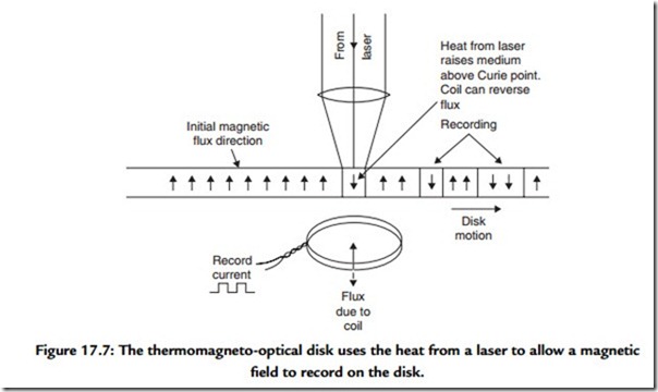
When a magnetic material is heated above its Curie temperature, it becomes demagnetized, and on cooling will assume the magnetization of an applied field which would be too weak to influence it normally. This is the principle of magneto-optical recording used in the Sony MiniDisc. The heat is supplied by a finely focused laser; the field is supplied by a coil that is much larger.
Figure 17.7 assumes that the medium is initially magnetized in one direction only. In order to record, the coil is energized with the waveform to be recorded. This is too weak to influence the medium in its normal state, but when it is heated by the recording laser beam the heated area will take on the magnetism from the coil when it cools. Thus a magnetic recording with very small dimensions can be made.
Readout is obtained using the Kerr effect, which is the rotation of the plane of polarization of light by a magnetic field. The angle of rotation is very small and needs a sensitive pickup. The recording can be overwritten by reversing the current in the coil and running the laser continuously as it passes along the track.
A disadvantage of magneto-optical recording is that all materials having a Curie point low enough to be useful are highly corrodible by air and need to be kept under an effectively sealed protective layer.
All optical discs need mechanisms to keep the pickup following the track and sharply focused on it.
The frequency response of an optical disc is shown in Figure 17.8. The response is best at DC and falls steadily to the optical cut-off frequency. Although the optics work down to DC, this cannot be used for the data recording. DC and low frequencies in data would interfere with the focus and tracking servos. In practice the signal from the pickup is split by a filter. Low frequencies go to the servos, and higher frequencies go to the data circuitry. As a result, the data channel has the same inability to handle DC as does a magnetic recorder, and the same techniques are needed to overcome it.
