WIRED NETWORKING TECHNOLOGIES
Wired networks use three types of cable: twisted pair, coax, or fiber optic. The telephone system has used twisted-pair cable from the very beginning and it is still in use today. It is also the predominant way that LANs are interconnected. Coax cable was once popular but is not widely used today except in cable TV systems. Fiber optic cables were not practical until the 1970s, but since then have been developed into the best way to wire computer networks because of their high speed and low loss.
Types of Cables
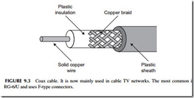
Coax cable was the original networking medium (see Figure 9.3). It has a copper wire center conductor surrounded by an insulator like Teflon or another type of plastic, which in turn is usually covered with a wire-mesh braid.
A plastic outer jacket covers the whole thing. The center wire and the mesh are the two connection points. Coax can handle frequencies up to many gigahertz. But it has high losses over long distances. Coax is mainly used in cable TV networks.
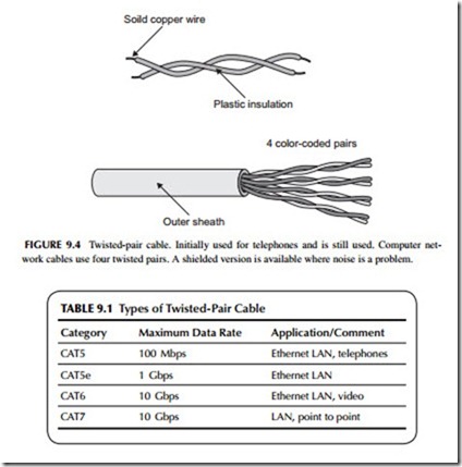
Twisted pair is the widely used cable for telephones and LANs. It consists of two solid insulated wires twisted together as shown in Figure 9.4 . Most telephone or LAN cables contain multiple pairs. Typical LAN cables have four pairs in a single cable. These cables are standardized and categorized as shown in Table 9.1. CAT5 and CAT5e are the most common. The eight wires are usually terminated in a connector called an RJ-45.
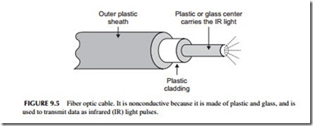
Fiber optic cable consists of a thin glass or plastic center piece surrounded by a plastic outer cover. Then that is further wrapped by an outer plastic covering (see Figure 9.5). Light waves are passed down the center glass or plastic cable. Most light comes from an infrared (IR) light laser. You cannot see IR but it is light nonetheless. IR light is what your TV remote control uses. The IR light is pulsed off and on to create binary signals. These are picked up
at the receiving end by a light detector and converted back into binary 0 and 1 voltages (see Figure 9.6).
Over the years, dozens of different wired networks have been developed. But in the past two decades, only two types of wired networks are dominant: Ethernet and Sonet.
Ethernet
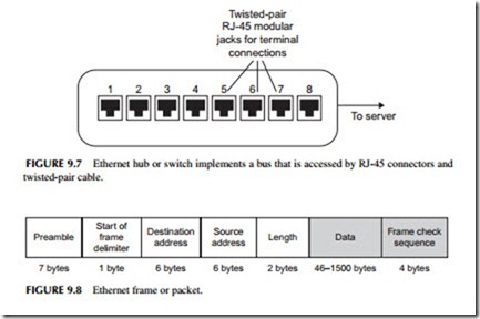
Ethernet was originally developed as a LAN in the 1970s. It used coax cable in a bus topology to interconnect multiple computers. Ethernet is also known by its Institute of Electrical and Electronic Engineers (IEEE) standard designation 802.3. There are many variations of this technology, but the most common one uses unshielded twisted-pair cable. The bus topology is generally implemented inside a piece of equipment called a hub or switch (see Figure 9.7). The cable from each computer or other device is connected to one of the jacks on the hub or switch. The hub or switch connects to a master computer called a server that manages the network. Generally speaking, connections to the hub or switch are limited in length to about 100 meters or 300 feet.
The initial Ethernet LAN had a maximum data rate of 2.93 Mbps over coax. When Ethernet was standardized, the basic data rate was 10 Mbps. Over the years, Ethernet has been improved and developed to create versions with data speeds over twisted-pair cable of 100 Mbps, 1 Gbps, and 10 Gbps. While 10 Mbps can be implemented over a single twisted pair, to achieve speeds of 100 Mbps, 1 Gbps, and 10 Gbps, all four twisted pairs in the CAT5 cable are used. The data is divided between and transmitted in parallel at the same time using special multilevel encoding that permits such higher data rates to be achieved.
There are also versions of Ethernet that use fiber optic cable. Fiber optic cable is normally used on the 1-Gbps and 10-Gbps versions. The latest versions of Ethernet provide 40-Gbps and 100-Gbps data rates.
How Is Ethernet Used?
Ethernet uses a bus topology connection where only one node can transmit at a time. This requires the use of an access method that permits the nodes on
the bus to share it. Ethernet uses a technique known ascarrier sense multiple access with collision detection (CSMA/CD). This is part of the IEEE 802.3 standard. Essentially what happens is that if a computer wants to transmit, it monitors the bus, and if no one is transmitting, it will begin transmitting its signal. If someone else tries to transmit at the same time, a collision occurs and both computers stop transmitting. Each will wait a random period of time and then try again. Whoever captures the bus first will be allowed to transmit. The data is transmitted over the bus and any computer connected to it can receive it. However, typically the transmission is only intended for one other computer. To identify that computer, each is given an Ethernet address that is transmitted along with the data to be sent.
The data to be transmitted are packaged together in a group of bits called a packet. Figure 9.8 shows what a typical Ethernet packet looks like. The pre- amble consists of 7 bytes of alternating 1’s and 0’s that help the receiving computer establish clock synchronization with the transmitting computer. The start frame delimiter presents a unique 1-byte code indicating that a frame of Ethernet data is to be transmitted. Next, a 6-byte destination address identifies the desired receiving node. The next 6 bytes identify the sending node. This is followed by another 2 bytes of data that indicate how long the data message is. The block of data is then transmitted. It can be any length from about 46 to 1500 bytes. The packet ends with a frame check sequence that is essentially a unique code designed for error detection and correction. If bit errors occur during transmission, the receiving computer can perform specific logic functions that allow the error to be detected and then corrected.
While Ethernet started out as a LAN, it has morphed into other larger forms of networks. Because of its high-speed capability with fiber optic cable, it is also used to form MANs and even WANs. A special version for MANs and WANs is called Carrier Ethernet. There is also a version of Ethernet used in storage area networks, called Internet Small Systems Computer Interface or iSCSI. There is also a wireless version of Ethernet that will be discussed in another section in this chapter.
Sonet
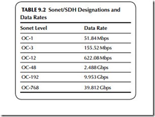
Sonet means synchronous optical network. Also known by its international standard name, synchronous digital hierarchy, this fiber optic network sys- tem was designed specifically for high-speed data transmission in telephone networks and computer systems. Basically, Sonet defines how data is trans- mitted over the fiber optic cables. This includes the data format as well as data speeds. Table 9.2 shows the various standardized transmission speeds from 51.84 to 39.812 Gbps. The bulk of Sonet installations, which are used primarily in the telephone networks and the Internet, use 2.488 Gbps (also generally called 2.5 Gbps) and 9.953 Gbps (generally referred to as 10-Gbps Sonet). More recently, new 39.812 (40) Gbps networks are being built for the Internet. Data is transmitted in fixed-length frames made up of 810 bytes, most of which is data. The network topology is either point to point or i n a ring.
Most big WANs and MANs use the Sonet system. However, Sonet is often used to transmit other data, including the telephone company T1 and T3 line data, asynchronous transfer mode (ATM), frame relay, and other telephone company formats. It is also widely used to carry Ethernet packets as well as the unique packets that are part of the Internet protocol.
Telephone Data Systems
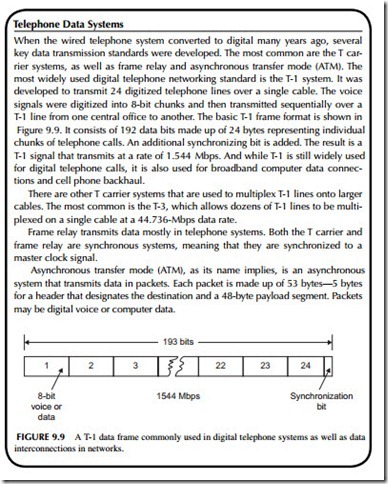
When the wired telephone system converted to digital many years ago, several key data transmission standards were developed. The most common are the T car- rier systems, as well as frame relay and asynchronous transfer mode (ATM). The most widely used digital telephone networking standard is the T-1 system. It was developed to transmit 24 digitized telephone lines over a single cable. The voice signals were digitized into 8-bit chunks and then transmitted sequentially over a T-1 line from one central office to another. The basic T-1 frame format is shown in Figure 9.9. It consists of 192 data bits made up of 24 bytes representing individual chunks of telephone calls. An additional synchronizing bit is added. The result is a T-1 signal that transmits at a rate of 1.544 Mbps. And while T-1 is still widely used for digital telephone calls, it is also used for broadband computer data connec- tions and cell phone backhaul.
There are other T carrier systems that are used to multiplex T-1 lines onto larger cables. The most common is the T-3, which allows dozens of T-1 lines to be multi- plexed on a single cable at a 44.736-Mbps data rate.
Frame relay transmits data mostly in telephone systems. Both the T carrier and frame relay are synchronous systems, meaning that they are synchronized to a master clock signal.
Asynchronous transfer mode (ATM), as its name implies, is an asynchronous system that transmits data in packets. Each packet is made up of 53 bytes—5 bytes for a header that designates the destination and a 48-byte payload segment. Packets may be digital voice or computer data.
Optical Transport Network
The optical transport network (OTN) is a technology used to implement the Internet backbone network. This is the core long haul fiber optical network that connects the world together. OTN uses special polarization and modulation techniques to transmit data rates of 40-Gbps and 100-Gbps.
