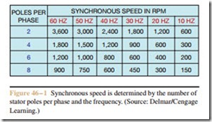
The speed of a three-phase induction motor can be con- trolled by either changing the number of stator poles per phase, as is the case with consequent pole motors, or by changing the frequency of the applied voltage. Both methods will produce a change in the synchronous speed of the rotating magnetic field. The chart shown in Figure 46 – 1 indicates that when the frequency is changed, a corresponding change in synchronous speed results.
Changing frequency, however, causes a corresponding change in the inductive reactance of the windings (XL = 2pfL). Since a decrease in frequency produces a decrease in inductive reactance, the amount of voltage applied to the motor must be reduced in proportion to the decrease of frequency in order to prevent overheating the windings due to excessive current. Any type of
variable frequency control must also adjust the output voltage with a change in frequency. There are two basic methods of achieving variable frequency control: alternator and solid state.
Alternator Control
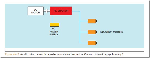
Alternators are often used to control the speed of several induction motors that require the same change in speed, such as motors on a conveyer line (Figure 46 – 2). The alternator is turned by a direct current motor or an AC motor coupled to an eddy current clutch. The out- put frequency of the alternator is determined by the speed of the rotor. The output voltage of the alternator is determined by the amount of DC excitation current applied to the rotor. Since the output voltage must change with a change of frequency, a variable voltage DC supply is used to provide excitation current. Most controls of this type employ some method of sensing alternator speed and make automatic adjustments to the excitation current.
Related posts:
Incoming search terms:
- controlling the frequency output of AC generator
- frequency control of alternator
- frequency control in alternator
- concept of frequency control in
- variable frequency alternator
- The alternator is turned by a direct current motor or an AC motor coupled to a(n) ____________________ current clutch
- speed control of alternator
- how to control frequency in alternator
- how to control alternator speed
- how to change frequency of an alternator
- how can we control the frequency of alternator
- frequency control techniques in alternator
- frequency chnge in alyernator
- concept of frequency control in alternators
- Concept of frequency control in alternator
- voltage control method of alternator

