EQUALISERS AND MIXERS
The output of phonograph cartridges and tape player heads is not flat. So, there is a need for a certain amount of tonal modification to make the reproduced sound more believable. In all but the simplest installations, equalisers, mixers and filters are needed for one reason or another. In the simplest installations the functions are necessary, but they usually are built into the single-unit amplifier.
EQUALISERS
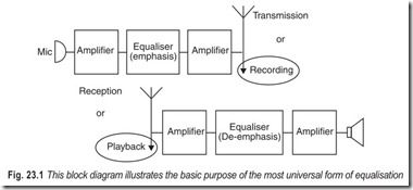
The most universal use for equalisers is in complementary pairs to make the best use of a storage or transmission medium (Fig. 23.1). The ideal system reproduces sound with the various component frequencies in the same proportions received at the input to the system. But these proportions are not ideal for recording on disc or tape, or for radio transmission.
The principal factor in all equalisation theory is that the higher frequencies in the audio spectrum, while they are the most readily audible, possess the least energy content. Consequently, background noise is most noticeable in the form identified as “hiss.” Equalisation emphasises these higher frequencies before recording or transmission, and removes the emphasis during playback or reception reproduction, thus reducing background noise attendant upon the form of record or transmission. So equalisation is incorporated in the recording equipment, or at the radio transmitter, to yield a better overall signal-to-noise ratio, and improve dynamic range. Then the complementary equalisation is needed on playback or reception to reconvert the component frequencies to their original proportions.
While all equalisation serves this general purpose, the precise form varies from medium to medium. For true reproduction, the equalisation on playback or reception should complement or match that used in recording or transmission.
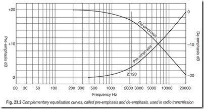
For radio reception, particularly the equalisation consists of “de-emphasis.” In transmission, frequencies above a turnover point of 2,120 Hz are simply emphasised at 6 dB/octave. The receiver needs to roll off at 6 dB/octave with the 3 dB point at 2,120 Hz (Fig. 23.2).
For disc recording, European standards differ from the American. So any facility that may handle both sources of records needs to provide equalisation facilities for both.
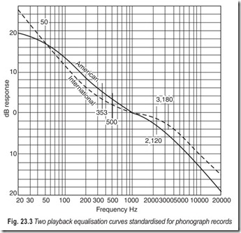
The American equalisation for playback, assuming a velocity-type pick-up (which most professional pick-ups are), has three important reference frequencies—50 Hz, 500 Hz, and 2,120 Hz. At the first the response turns from what would be flat (constant velocity) at frequencies below 50 Hz to a 6 dB/octave downward slope (to correct for constant amplitude over this range). At the second frequency the response reverts toward constant velocity (flat) and at the third point it again resumes its downward slope to compensate for constant amplitude over the highest frequencies (Fig. 23.3).
The European or international equalisation, while basically similar, uses different reference points. The first turnover of the American curve is missing (constant-amplitude recording extends downward definitely from the lower turnover). This, in itself, makes little difference, since not much is recorded that low in the frequency range. Instead of the 500 Hz turnover, the international equalisation uses 353 Hz, and instead of 2,120 Hz the international is 3,180 Hz. This means that the overall international playback curve shows more “levelling off” in the middle than the American curve (Fig. 23.3).
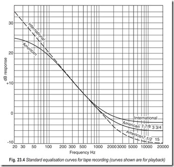
A similar difference exists between the American and the international standards for tape equalisation. Both use a 6 dB/octave downward slope through the major part of the audio range. The American levels off at the low-frequency high-level end, with a turn over point at 50 Hz (like the disc equalisation) while the international standard doesn’t have this turnover at all. Both level off at the higher-frequency low-level end, the American with a turnover at 3, 180 Hz for speeds of 7.5 and 15 inches per second, and at 2, 120 Hz for speeds for speed of 1.875 and 3.75 inches per second. The turnover on the international curve is at 1,500 Hz (Fig. 23.4). So any facility that expects to use tapes from all sources needs these different equalisations available.
LOUDNESS COMPENSATION
Another need for equalisation arises from playing program at a level different from that at which it is recorded or picked up. For example, background music systems, unless they use specially recorded music, play at a much lower level than the program is normally reproduced. Without equalisation it seems to lack character, because all of the lower frequencies, and some of the extreme highs, seem to disappear due to reduced sensitivity of the average human hearing facility in these frequency ranges at reduced levels.
So programs of this kind need loudness equalisation. The same is true for programs containing dialogue or action effects with background music. When mixers are used to put such programs together, the channels containing background music need loudness compensation equalisation. However, this kind of equalisation is best made flexible so it can be adjusted until it “sounds right.” For some home high fidelity systems, the manufacturers incorporated what they termed a “loudness control” in which this compensation was made automatically as volume is turned up and down, which at first seemed like a good idea. A loudness control that incorporates automatic response compensation for changes in setting requires a separate level control for each program input, so the response to each program is correct at all settings of the loudness control. This is needed to compensate for differences in level of recording or transmission that do not reflect intended changes in reproduced loudness.
Some recordings employ a higher peak level than others. In the system these peak levels should all be the same, a limit set by the handling capacity of the system. If the loudness control is used to set levels for this purpose, the equalisation at maximum loudness on each program will differ according to the recorded or transmitted volume level of that program. For the professional operator, it proves far simpler to provide separate bass and treble controls. In fact, most high fidelity systems have reverted to this method, for the same reason.
Tone controls also can be used to enhance the voice quality of individuals before a microphone, especially in an auditorium with poor acoustic qualities, which always seems to emphasise poor speech qualities. One individual may have a deeply resonant bass voice that comes out overly muffled in a poor acoustic environment. Bass needs reducing and maybe treble needs reinforcing to make this individual’s voice sound balanced, or even “natural” for that individual.
Another individual may have a shrill, edgy voice, which the acoustic environment also tends to emphasise. The reverse treatment is needed for this person. Just as there may be some argument about whether a camera really presents a true picture, so there is no doubt that a sound system does not accurately represent individual voice qualities but tends to “caricature,” if not to outrightly distort, especially in a poor acoustic environment.
Sometimes, rather than accentuating one end or other of the frequency spectrum, a person’s voice seems to “grate” on one note, perhaps one that may seem to want to excite an acoustic howl. An experienced speaker will often inflect his voice to avoid the effect, but many who speak into microphones use their normal voice and seem unable to modify it to suit the needs of the moment. So, then, the system should be able to play down that particular area in the frequency spectrum, until that person’s voice no longer “grates” at the particular frequency.
Requirements to achieve these variations in different environments will change from installation to installation. Those with better overall acoustics will not require much help in this department, and minimal control, say simple bass and treble lift and cut, may be quite adequate. But a system installed in a poor acoustic environment may need a more comprehensive set of controls, one that divides the spectrum into three or more bands with separate level controls for each. How many such controls are needed also may be subject to variation from one installation to another. In the better acoustic environment, one set of tone controls for the whole system will suffice. In the poorer one it may be advisable to have two or more available for use on different microphone channels. Or, if two people are likely to share one microphone for an interview type presentation, it may be advisable to have alternative controls on the one input, with a key that can change from one to the other, according to which of the parties is speaking at a particular moment.
One more kind of equaliser sometimes used is called a “presence equaliser.” It has been found that a reproduced program which sounds “lifeless” or as “lacking presence” can often be enlivened by slightly
emphasising frequencies centered about 3,000 Hz and extending from about 1,500 Hz to about 6,000 Hz. Not more than 6 dB maximum boost achieves this, and often a smaller boost is sufficient. An adjustable equaliser of this type is a useful adjunct on some installations.
TYPES OF EQUALISERS
Whatever equalisers are used, they may be one of two major types—active or passive. The latter are the simplest, but inserting them in a circuit involves a loss of gain. Only at a maximum boost point will the overall gain approach the level of transmission in the absence of the equaliser. This means that additional amplification is needed whenever passive-type equalisers are used, so that normal level is maintained. A 20 dB line amplifier is useful for this purpose and consoles with many equalisers usually have an equal number of patchable line amplifiers so the level can be maintained.
Mistakes can be avoided by including a line amplifier with each equaliser, so it is automatically included when the equaliser is patched in. This makes patching more foolproof. But if the two are going to be put together, anyway, why not use the amplifier to improve the equaliser? This leads to theactive equaliser, a unit that includes gain so the mid-band level is unchanged from input to output. Feedback is used to reduce distortion to the maximum degree at any frequency. With the active type a boost is really a boost; with the passive type a boost is merely a lack of attenuation present everywhere else.
MIXERS
Mixers are controls whose purpose is to mix various elements of program together—the action centre of an audio system. For this reason considerable attention has gone into their design over the years. Two areas have received concentrated attention: (1) making the operation silent and durable; and (2) making it easy to use with an action involving natural human reflexes. Any contact that is used as a “slider,” virtually continuously, is liable to deteriorate with long use. This has led to the development of contacts with a minimum tendency to oxidise or wear, and with self-cleaning action.
Making such controls easy to manipulate placed emphasis on knob design so that the position would be easily recognisable at a glance, and also make it easy to change settings, if possible, with only a finger for each control, in such a way that each hand could control several knobs simultaneously. The final improvement that has now become almost universally accepted is a control operated by a linear lever instead of a rotating knob. This not only makes the individual control positions instantly visual but manually functional as well. It also enables closer grouping so that the hand can encompass a greater number of controls for simultaneous manipulation.
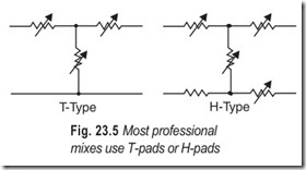
Electrically, mixers introduce loss, depending on how many controlled circuits are connected together for mixing. So, as with equalisers, extra gain must be provided so the output is at the proper level. Mixers can work in several ways. Most professional mixers of the passive type use T-pads, or if the circuits are balanced, H-pads (Fig. 23.5). Each pad is designed in steps so that movement from one stud to the next changes level by a fixed amount, say 1.5 dB, when the pad is correctly terminated, partcularly at the output end.
One way of combining mixer pads is to parallel their outputs and terminate the combination with a resistance value 1/nth of their working impedance, where n is the number of circuits mixed. This is the most efficient form of mixing, yielding the minimum loss for a given number of circuits, referred to the full-on position of individual circuits. Its disadvantage, where the sources are passive (resistive), is that loading the output with an impedance much lower than the characteristic value causes the last few steps to act quite drastically; that is, introduce more than the designated dB per stud.
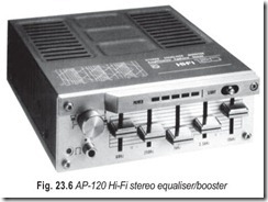
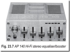
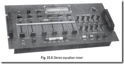
Typical professional equalisers and mixers are shown in Fig. 23.6 through 23.10. Equipment specifications are also included.
AP–120 hi-fi stereo equaliser/booster □ Under dash/console mounting □ Meets DIN 45 500 and NFC 97–420 requirements □ Five + 12 dB slider controls operating at 60, 250, 1000, 3500 and 10,000 Hz
□ Two-way/four-way speaker system □ Frequency response 40–20,000 Hz + 1.5 dB □ DIN 45 324 :
2 × 20 W + 1 dB cont. sine wave at THD 10% □ DIN 45 500:2 × 10 W cont. sine wave at THD < 0.7% □ Music Power : 2 × 12 W cont. sine wave at THD < 0.7% □ NFC 97–420 : 2 × 10 W cont. sine wave at THD
< 0.5% □ Output power LED bar. Diffused front illumination □ Dimensions 50 mm (H) × 140 mm (W) × 165 mm (D)
AP–140 hi-fi stereo equaliser/booster □ Under dash/console mounting □ Five + 12 dB slider controls operating at 60,250, 1000, 3500 and 10,000 Hz □ Two-way/four-way speaker system □ LED output monitor □ Frequency response 60–20,000 Hz + 3 dB □ 2 × 16 W + 1dB cont. sine wave power at D < 10% □ 2 × 9 W + 1 dB cont. sine wave power at D < 1% □ Dimensions 50 mm (H) × 140 mm (W) × 165 mm (D)
TUAC Discotheque mixer with auto fade Specification: Deck Inputs–50 mV into 1 MΩ: Deck Tone Controls–treble + 20 – 10 dB at 12 kHz, Bass + 22 – 15 dB at 40 Hz; Mic Input – 200 ohms upwards, 2 mV into 10 kΩ; Mic Tone Control–Total Variation Treble 15 dB, Total Variation Bass 10 dB; Tape Input – 30mV into 47kΩ;
Power Requirements–30–45 volts at 100 mA. Stereo equaliser mixer-A 2570
MAXIMUM INPUT LEVEL (clipping) 6.9 volts
S/N RATIO (re 0.5 VOLT; A weighting; IHF loading) all controls at 0 dB 92 dB wrost case (at max. above 1 kHz, other at min.)
Harmonic Distortion (THD; 20 Hz to 20 kHz) at 1-volt output < 0.014%
at 2-volt output < 0.027%
Frequency Response (all controls at 0 dB)
+ < ¼, – ¼ dB, < 10 Hz to 153 kHz;
+ < ¼, – 3 dB, < 10 Hz to 219 kHz
Control Action (max. & min. with other controls at 0) EQ–One Series II
Infrasonic Filter –3dB at 22 Hz; ≈ 18 dB/octave
Channel Separation (at 1 kHz) 74 dB
Input Impedance > 23.7k ohms
Output Impedance 69 ohms
Dimensions: 19 by 5¼ inches (front panel), 7½ inches deep plus clearance for rack-mount handles, controls, and connections.
EXERCISES
Descriptive Questions
1. What is the need for tonal modification?
2. Explain the basis of equalisation theory.
3. How many types of equalisers are there? Explain briefly.
4. Justify the statement “mixers are the action centre of an audio system”.
5. What type of controls are used with mixers?
Fill in the Blanks
1. The higher frequencies in the audio spectrum possess the energy content.
2. Background noise is most noticeable in the form identitified as .
3. Tone controls can be used to the quality of sound.
4. A system installed in poor acoustic environment may need a more set of controls.
5. Additional amplitification is needed when equalisers are used, so that normal level is maintained.
6. Mixers are the centre of an audio system.
7. With equalisers gain must be provided so the output is at level.
8. Mixers introduce depending on how many controlled circuits are connected together for mixing.
ANSWERS
Fill in the Blanks
|
1. least |
2. hiss |
3. enhance |
|
4. comprehensive 7. extra, proper |
5. passive-type 8. loss |
6. action |
