MAGNETIC RECORDING AND REPRODUCTION
Cassette recording was originally devised as a cheap, simple-to-operate system for tape recorders, designed to appeal to a mass market. At a time when the sales of reel-to-reel recorders were encountering resistance due to the cumbersome threading procedure, the size of the reels and the weight of the machines, cassette recording, with the simple snap-in loading mechanism rapidly gained in popularity. Cassette recorders now account for practically all home recorder sales outside the semi-professional and hi-fi markets.
MAGNETIC RECORDING
All of the work in the recording studio makes use of the magnetic tape recorder. The ideal recorder would be a memory bank of perfect accuracy with an unlimited capacity for storing separate groups of information in a constant time relationship. The ideal recorder must be able to store the sound heard in the monitor speakers so that they can be played back at a later date, exactly re-creating the sounds heard from the mikes. Magnetic tape is at present the accepted and the most practical means for recording. It has advantages over direct recording into disc as multitrack format, editing and over dubbing are possible.
The theory of tape recording is based on relating physical lengths of tape to periods of time. By playing back each section of a length of tape at the same speed at which it was recorded, the original rhythm and duration of each sound and the spaces between sound are preserved. The best way of ensuring that the time spectrum remains unchanged whenever the tape is played is to record and play it back at a constant speed.
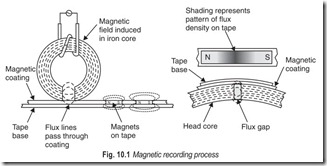
Sound vibrations can be recorded as a pattern of varying degrees of magnetisation on a plastic ribbon impregnated with a plastic material. The tape moves at a constant speed across the poles of an electromagnet, which are less than 0.1 mm apart. The electrical output from a microphone is supplied to the electromagnet and controls the magnetic field between the poles. Thus, the section of tape bridging the poles at any instant is magnetised to a degree controlled by the sound vibration (Fig. 10.1).
MAGNETIC PLAYBACK
All methods of recording and reproduction rely on a sequence of reversible processes with sound vibrations at one end of the sequence and a lasting change produced in some other property at the other end.
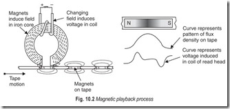
During playback the magnetised tape recording is moved at the same speed past the poles of the magnet and induces a field in the magnet. This, in turn, induces a current in the windings, which can be amplified to reproduce the original sounds, as shown in Fig. 10.2. In practice, all these changes are superimposed on a very high frequency current of about 80 kHz, which acts as a carrier wave for the low-frequency vibrations.
The amplitude of the voltage across the head coil depends on the rate of change of flux in the core assuming constant speed. This is, in turn, dependent on both the strength of the recorded magnet and the sharpness of the recorded magnet.
The process of magnetic playback is thus the reverse of the process of magnetic recording.
MAGNETIC ERASING
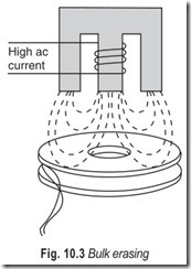
The erasing of magnetic tape is done in one of three ways. The first, and simplest, method is to place an entire reel of the tape in a strong alternating magnetic field as shown in Fig. 10.3. This leaves the tape in a somewhat unpredictable magnetic state. It is termed bulk erasing and is more useful for removing recorded information from tape.
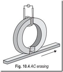
The second method of erasing tape is to move the tape past a recording head in which there is a high-frequency alternating current, as shown in Fig. 10.4, This is termed ac erasing, and essentially neutralises the tape’s magnetic properties.
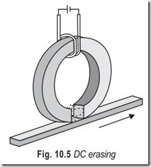
The third method is to move the tape past a recording head in which there is direct current as shown in Fig. 10.5. This is termed dc erasing, and essentially magnetises the tape uniformly along its entire length,thus turning it into one long thin magnet.
RECORDING MEDIUM
There are two types of recording medium in general use. The first uses a thin coating of magnetic oxide and the second a thin layer of metallic magnetic film.
The magnetic oxides which are most often used are those of iron, usually gamma ferric oxide (Fe2O3) but sometimes ferrous oxide (Fe3O4 ) is also used. More recently chromium dioxide has been employed to achieve better packing density and greater output signals. All these oxides are produced in the form of fine acicular particles with a length-to-diameter ratio of at least ten to one. Typical lengths of these particles range from a few microns to a few tens of microns.
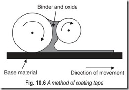
The process of coating magnetic tape is illustrated in Fig. 10.6. The oxide is mixed with a fluid containing a resin type binder and applied in a thin layer to the tape base material. The tape then passes through a drier to evaporate the solvents. This is often done in the presence of a magnetic field to orient the oxide particles for better performance. After drying the tape is passed into a machine which slits it from its original width, which can be as much as 1.5 m, into its final size of one or two cms. The thickness of the coating produced for memory system applications is critical and must be controlled to a few per cent. Typical coatings range from Fig. 10.6 A method of coating tape 1 to 25 µm in thickness and are usually about 5 µm. In general, tapes with the thinnest coatings are capable of the highest information packing density.
Some of the main problem areas in producing tape in this way are those of obtaining a coating with uniform magnetic characteristics over the whole tape width and of avoiding clusters of magnetic particles which give rise to noise, dropouts and tape wear. The uniform coating is obtained by careful control of the original layer of oxide and resin by various smoothing techniques to remove irregularities. Clusters are minimised by choice of particle size, basic solvent and by very thorough mixing in a ball mill before use. By careful control and inspection of the manufacturing process, dropout free lengths of greater than 500 m are regularly produced for computer applications. A dropout is defined as a decrease in signal of 50%.
Metallic thin magnetic films have an advantage over oxides in that they can be controllably produced in much thinner layers by electroplating and other techniques. They tend to be more sensitive to mechanical forces and therefore are usually deposited on to rigid bases. The most frequently used films are nickel– cobalt alloys and these are produced in thickness ranging from 0.2 to 2µm. A wide variety of magnetic characteristics can also be produced by varying the composition of the alloy and by adding very small quantities of other elements. Great care must be taken to prepare a smooth base for the deposition of the thin film in a stress-free state. This, of course, is necessary with oxide coatings. The smooth surface which results from the use of metallic films enables recording heads to run closer to the magnetic surface and thus achieve better performance. The main manufacturing problems are again those of achieving a uniform magnetic coating over a large surface and of preparing this surface to receive the film.
Plastic tape is made in various types to satisfy various performance and price requirements. For example, a relatively thick tape (one-and-a-half mil) is used when strength and dimensional stability of the tape are primary considerations. When optimum tape-to-head contact is required (for optimum data resolution) a thinner tape (1 mil or less) having greater flexibility is used. When optimum reliability is required, a tape that is fully certified and heavy duty is used. A fully certified tape is one that has been factory tested to ensure that the entire area of the tape used for recording has minimum number of “bad spots” that cannot be recorded correctly. A heavy-duty tape is one that uses a “hard” binder (in the oxide coating) that is highly resistant to wear. Typical heavy-duty tape is capable of being passed over the head more than 500 times before the data must be re-recorded, and more than 20,000 times before showing signs of wear. Even when sign of wear is evident, the tape can be cleaned and reconditioned to enable continued usage.
MAGNETIC HEADS
Most of the developments which have taken place to improve the quality and usefulness of magnetic tape recording have centred on recording and replay heads, the successors to the old horse shoes. The shape of the tape head is roughly that of a horse-shoe magnet wound with a coil of wire, but with the gap between the pole pieces reduced to an incredibly small distance. Tape head gaps are now measured in thousandths of a millimeter (µm) or millionths of an inch, and the size of the gap, particularly for replay, must be as small as can be kept consistent in manufacture remembering that the gap dimension must be the same for each part of the tape covered by the gap and must not vary greatly from one sample of head to another.
The reason for keeping the gap so small is that the ability to record and replay high-frequency sounds depends critically on this gap size and on the speed at which the tape is taken past the gap.
Imagine, for example, that the gap is one thousandth of an inch (0.025 mm). Each magnetised portion of the tape must therefore be at least 0.001 in (0.025 mm) in length, so that a complete wave would need a strip of tape at least 0.002 in (0.050 mm) long to record. Now if we are trying to record a frequency of 5000 Hz (5 kHz) meaning 5000 complete waves per second, the length of tape which must pass the head per second is 5000 × 0.002 in which is 10 in/s (25.4 cm/s). For a frequency range of up to 10 kHz, which is only starting to be tolerable by modern standards, the tape speed for the 0.001 in (0.025 mm) gap would have to be at least 20 in/s (50.8 cm/s), and this might prove only barely adequate. Such high tape speeds were used in early recorders, but they require enormous lengths of tape on large reels if recordings of any useful length are to be made. The use of modern micro-gap heads has now made possible the use of tape speeds as low as 1 7/8 in/s (4.76 cm/s) as used in cassette recorders.
A corresponding improvement in technology has taken place in the materials used for tape heads. Early tape recorders used heads made by the simple process of winding steel ribbon round a cylinder to several layers of thickness, welding the ends, removing the cylinder and sawing a gap in the layers. A coil of insulated wire was then wound round to complete the construction of the head. Such primitive methods are no longer used, because it is impossible to attain the small gaps required, and the steel wears rapidly as the tape, which is quite abrasive, passes over it.
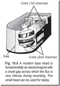
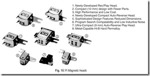
Modern tape heads, Figs. 10.8 and 10.11, are constructed either of special quality nickel–steels, which have excellent performance, but wear out in, perhaps, five years or so, or from modern non-metallic materials. Modern techniques have been devised for using the non-metallic but magnetic materials called ferrites, which are then finished to a glassy surface. It is now possible to make such materials into heads withremarkably small gaps and performance almost equal to that of the nickel–steels but highly resistant to the rubbing of the tape, so much so that such heads can be guaranteed for ten years or more.
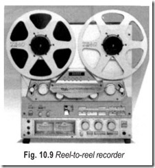
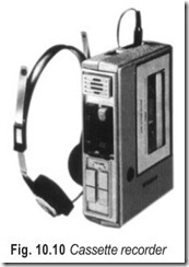
Though some quality reel-to-reel machines, Fig. 10.9, use separate record and replay heads, usually with different gap dimensions, it is usual on cassette recorders to have only one head for both recording and for replay. This considerably limits the creative possibilities of the cassette recorder, since it is not possible to transfer recordings from one track to another, nor to record on one track while another is playing. Such requirements, however, belong more properly to the world of professional or semi-professional recording, whereas cassette recorders, Fig. 10.10, are exclusively instruments of amateurs interested more in reproducing music than in creative work.
Yet another requirement of a recorder is erasure, since one of the attractions of magnetic tape recording is that unwanted recordings can be erased and replaced by new recordings. Erasure in any kind of magnetic recording is carried out by another head using a much wider gap and wound with a coil to which is supplied a current signal of much higher frequency than any recorded sound signal. Frequencies ranging from 75 to 120 kHz are now common. Such a signal applied to a comparatively wide-gap head cannot be recorded on the tape, and has the effect simply of jumbling the magnetism of the tape particles so that the information is erased by removing the alternate changes in direction of magnetisation of the particles in adjacent pieces of tape. In normal use, and inevitably in cassette recorders, the tape passes over the erase head before passing over the record/replay head, and the erase head is activated only during recording, so that the tape is automatically erased before being recorded.
CASSETTES
The cassette is actually quite a complex piece of machinery. For example take the shell. In order to operate properly, the dimensions of the shell have to be extremely accurate. A good shell is precision moulded from high impact polystyrene. Many people think that all cassettes are alike. It is not so. The quality of the cassette used with the cassette recorder will determine whether or not the customer gets his money’s worth out of the system.
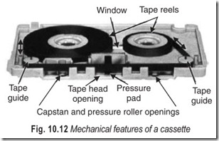
A cassette deck supplies only motion and electronics to the tape. Every thing else (Fig. 10.12), the tape, guidance system, tensioning devices, lubrication for the tape, and head-to-tape contact
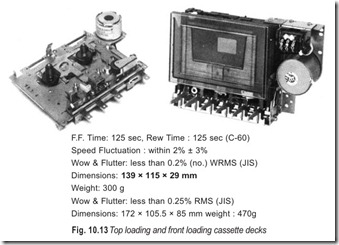
arrangement is built into the cassette itself. The cassette deck, Fig. 10.13, is no better than the cassette put into it.
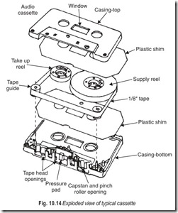
Each of the component parts, shown in Fig. 10.14, has a very specific function, and each must perform that function with complete reliability and great precision. The shell, for example, must be moulded to the exact dimensions called for in ISI specifications. If the tolerances are too wide, you won’t be able to get the cassette into the deck. If they are too narrow, you won’t be able to get proper alignment with the heads once the cassette is in the deck. The guide rollers are crowned and flanged for proper alignment with the heads and spin on stainless steel bearings. The pressure pad supplies the right amount of pressure for a good head-to-tape Fig. 10.12 Mechanical features of a cassette contact. The pressure pad assembly is felt backed with a plated phosphor–bronze spring. You can see how much tape is left through the window at the top. The slip-sheet (liner) lubricates the roll of tape as it moves back and forth in the cassette shell. The leader is pinned into the hub. The tighter you pull the leader the tighter it grasps. The tape is held on to the supply and take up hubs. The two halves of the shell join smoothly and precisely in the centre of the working face. The cassette is screw assembled. Exploded view of a cassette is given in Fig. 10.14.
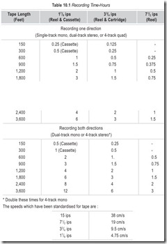
Cassettes are marked in terms of the duration of recorded program. A two-track cassette marked C60 will have a program of 30 minutes on each track.
The total thickness of the tape and its coating determines what length of tape can be wound onto a cassette. If only a short playing time is needed as in a C60 cassette (30 minutes each half) then a comparatively thick tape and coating can be used. The thicker tape makes for longer tape life with less risk of breakage or stretching. To obtain longer playing times, thinner tapes and coatings must be used, so that the risk of breakage and stretching is greater. One should not make valuable recordings on C 120 tape because their thin material is much more liable to stretch, deform, or break during rewind or play. Cassettes of different playing times—from the same manufacturer—will give different recording qualities, with different frequency ranges, noise levels and distortion levels for the same reading of VU meters during recording.
TAPE SPEEDS
Several different tape speeds are used in the studio. Most of the work is done at 15 ips (inches per second) because this speed allows all audio-frequencies at full level without saturating the tape and produces a good signal-to-noise ratio. In addition, this speed spreads out the recording signals far enough apart for easy editing.
Consumer hi-fi tape machines move tape at 7 1/2 ips in order to save tape. As a result most 1 4 –inch studio recorders operate at both 15 and 7 1/2 ips so that copies can be made for clients at the proper speed.
The 7 1/2 ips produces too much of a compromise in signal quality for use in recording multitrack master tapes, so 30 ips is sometimes available as a second speed. Recording at 30 ips produces a signal-to-noise ratio increase of about 3 dB as compared to 15 ips as well as increasing the resolution of the recording by doubling the length of tape corresponding to a particular time interval. This results in better transient response. The 15 ips recording is more prevalent than the 30 ips because all studios have 15 ips capability, while not all of them have the 30 ips speed, limiting the interchangeability of 30 ips tapes.
The upper limit of response (± 2 dB) at 7 1/2 ips is usually about 12,000 to 18,000 Hz and at 3 3/4 ips between 7,500 and 12,000 Hz. New designs operating at 1 7/8 ips are providing comparatively excellent frequency response. Don’t let a few hundred cycles of upper-limit frequency response be a final criterion in choice of a machine, because manufacturers differ in the rigidity and manner of making their tests. Listening is the best test.
Further reduction in speed is not possible due to problems of poor resolution associated with weak output.
Lower speeds, 9.5 and 4.75 cm/s, are used for long play in domestic cassette recorders. Higher speeds are used in good quality studio tape recorders.
MAXIMUM USABLE FREQUENCY
One cycle of variation covers a distance of one wavelength (λ) on the tape. If T is the time period in seconds then Distance covered = λ/T (speed) If S denotes the speed of the tape, we have
S = λ/T …(10.1)
= f λ (since f = 1/T)For optimum output, the gap-width should be half a wavelength of the maximum usable frequency (f ).
∴ fm= S/2G …(10.2)
Equation 10.2 gives the maximum usable frequency (fm ) in terms of tape speed S and gap width G. Thus,
increasing the tape speed increases the maximum usable frequency corresponding to reasonably good output.
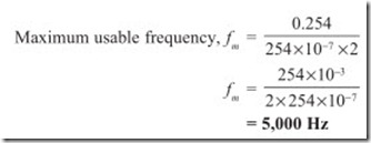
Example 10.1 If the gap width is 0.0254 mm and the tape speed is 25.4 cm/s find the maximum usable frequency.
Solution Gap width G = 0.0254 mm = 254 × 10–7 m
Tape speed, S = 25.4 cm/s = 0.254 m/s
Example 10.2 With a gap-width of 6 microns and a tape speed of 19 cm/s,calculate the maximum usable frequency.
Solution Gap width G = 6 microns = 6 × 10⁻⁶m
Tape speed, S = 19 cm/s = 0.19 m/s
TRACK CONFIGURATIONS
The term single-track recording indicates that only one track is being recorded on the tape. We might have a dual-track tape, but if only one track were utilised, it would be a single-track recording.
The width of standard reel-tape is 1/4 inch (250 mils.). Usually single-track recordings do not cover the entire width of the tape. If they did, we might not be able to erase the tape completely. Thus single-track recording widths usually vary anywhere from 0.118 to 0.245 in (118 to 245 mils), whereas the erase track is always about 0.006 in (6 mils) wider. If both the record and erase tracks were exactly alike in width, any misalignment would prevent complete erasure. Also by making the erase track wider we make sure that any leakage flux extending beyond the actual recording flux is also erased.
Dual-track recordings can be either monophonic or stereo. Basically, they call for recording two individual tracks on the 1/4 inch tape as shown in Fig. 10.16. In the monophonic mode, two methods of dual-track recording are possible. On older machines, one track is recorded, and when the end of the tape is reached, the supply and take up reels are interchanged manually, so that one becomes the other. Thus, if we recorded on the top portion of the tape on the first go-round, when we switched reels, we would again record on the top.
Another method is used on more recent machines. The machine automatically reverses itself at the end of the first recording. Then the tape winds itself back in the opposite direction. The reversing mechanism can be actuated mechanically or electrically. In mechanical methods when the tape is fully unwound after the first recording, the tension on the tape actuates a switch. This kicks the motor system into reverse, automatically changing the functions of the supply and take up reel. At the same time, the direction changing mechanism shifts the recording/playback head up or down to place it in contact with the track being recorded or played back. This is true only if a single head is used. If dual-track heads are stacked on top of one another, up and down shifting is eliminated.
In electrical methods a piece of metallic tape is fused to each end of the uncoated side of tape. When the tape reaches the end of its travel, these metallic pieces short circuit a pair of contacts thus closing an electrical circuit and setting the motor drive into reverse.
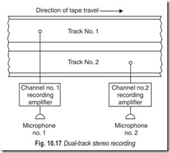
In dual-track stereo recording, both tracks are recorded simultaneously. The recording procedure can be accomplished in either of two ways. One method, Fig. 10.17, calls for the use of two discrete (separate) heads, staggered longitudinally about 1¼ inch apart, with one head higher than the other. This, the older system, has the disadvantage of requiring extremely accurate spacing between the respective head gaps to ensure that any stereo tape can be played on the particular machine. The staggered method has given way to the stacked head, or in-line method.
It is impossible to reverse dual-track stereo, reversal would erase what had been recorded previously. Hence, a new dimension has been added to tape, 4-track recording.
4-track recording is simply an extension of dual-track recording to permit reversal of the tape, add to record-playback time, cut the cost of the tapes, and permit quad recording.
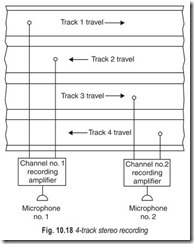
The method of recording stereo on 4-track tape is shown in Fig. 10.18. Note that tracks 1 and 3 are recorded in one direction (solid lines from recording amplifiers) whereas tracks 2 and 4 are recorded in the other direction (dotted lines from recording amplifiers). The tape itself, and the track spacing are shown in Fig. 10.19.
4-track tapes can also be used for monophonic recording. One can record upto eight hours of music on a single 7 inch reel. Furthermore, most of today’s pre-recorded stereo tapes are 4-track types.
TAPE TRANSPORT MECHANISM
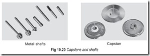
The term tape transport is a collective name given to the parts of a tape recorder that control the movement and handling of the tape. All machines employ a capstan, Fig. 10.20, to move the tape past the heads at a precise speed. A capstan is a precision cylindrical drum or spindle against which the tape is passed in order to maintain a constant tape speed. A pressure roller holds the tape, by spring pressure, against the capstan.
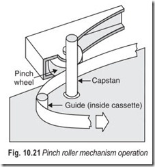
The capstan in a typical pinch roller tape drive mechanism rotates constantly under drive motor power. A pinch roller is positioned in a movable bracket close to the capstan so that it can be withdrawn from the capstan a few thousandth of an inch or it can be brought to bear on the capstan as shown in Fig. 10.21. The magnetic tape passes between the capstan and the pinch roller. When the pinch roller is withdrawn the tape does not contact the capstan and no tape motion occurs. To move the tape the pinch roller is forced against the tape and the capstan provides a tight capstan-to-tape contact.
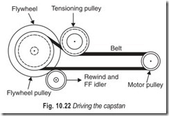
The most common arrangement for driving the capstan is shown in Fig. 10.22. The tape transport also provides for fast movement, forward or backward (fast forward or rewind) so that any desired portion of the tape can be located rapidly. Braking and pause functions are also associated with the tape transport.
Low priced recorders that dispense with capstan tape drive employ take-up-drive. The disadvantage of reel drive is that the tape moves slowly at first and then moves with increasing speed as the supply reel unwinds. Therefore, most machines are designed with capstan drive. Capstan diameters vary from 3/32 inch to 1 inch. Some professional tape recorders utilise interchangeable capstans of different diameters in order to change the speed of tape travel. The pressure exerted on the tape between capstan and roller must be sufficient to prevent slippage. However, excessive pressure accelerates wear of surfaces and bearing.
MECHANICAL CONTROLS
Two types of controls are fitted to cassette recorders, those which are mainly mechanical in action (though they may be electrically operated), and those which are purely electronic and act on the signal. Among the first group are the controls of tape wind, rewind and play; among the second group are the recording level controls and the record on/off switch. In addition to this grouping, some controls are used in everyday operation, some seldom, others (usually within the instrument) are set up during initial testing or in later servicing.
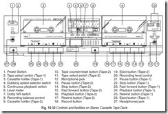
Taking the mechanical controls first, the most used mechanical controls are those which control the winding of the tape on the cassettes. On most cassette recorders, at present manufactured, these controls are operated by piano-type keys; depressing the key until it locks into position switches the control on. The mechanical keys of this group are the fast forward, fast rewind, record/play, pause, stop and cassette eject.
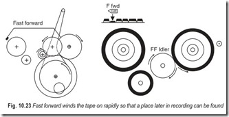
Fast Forward and Rewind : Fast forward winds the tape on so rapidly so that a place later in a recording can be found. During fast forward the tape heads are withdrawn from the tape and the amplifier is switched out of action so that no replay can take place. This avoids the twittering and clucking sound which would otherwise be heard as a recorded tape moves rapidly past the heads. With the heads withdrawn the idler wheel is also withdrawn and the tape is not pressed in contact with the capstan spindle. This avoids the spinning of the capstan at high speed (causing rapid wear) during fast forward. The tape drive during fast forward is carried by applying drive to the pickup reel on to which the tape is being wound within the cassette. This is done through the splined shaft over which the centre of the reel fits when a cassette is placed in the recorder. This is shown in Fig. 10.23.
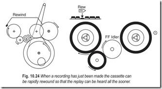
The arrangements for rewind, Fig. 10.24, are similar, though it is a common practice to make rewind slower than the fast forward. Rewinding of the tape is done so that a recording that has just been made can be heard all the sooner. In general, it is used more often than the fast forward.
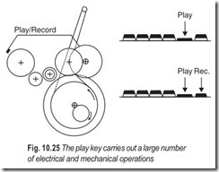
Play and Record : The play key carries out a large number of electrical and mechanical operations. During its operation power is applied to the capstan spindle motor and to the amplifier, the idler wheel moves so as to pinch the tape against the capstan spindle and the heads move forward to contact the tape, pressing it against the pressure pad housed inside the cassette. At the same time some drive must be supplied to the forward wind spindle engaged in the cassette pickup reel, so that the tape which is moved on by the capstan is taken up and evenly wound onto the pick-up reel. Where only one motor is used, this usually means a friction drive is applied by a pulley held between the motor spindle and the drive spindle by a light spring. Some slip must be allowed for, as the takeup spindle can’t be turned at a constant rate. When the takeup reel is empty, its radius is that of the wheel, about 1/2 inch (12 mm), so that one turn of the reel winds on the tape by about 3 in (76 mm). If the takeup speed is arranged so as just to keep the tape winding on at the beginning of the reel then there will be problems at the end of the reel when the radius of the takeup reel plus that of the tape is about 1 in and each turn winds on about 6 in (152 mm) of tape. Constant speed drive to the takeup reel is therefore not possible.When a separate motor is used for rewind, these awkward mechanical operations do not arise, and a light tension can be applied to the tape by connecting the motor to a voltage rather lower than is normally used for driving the takeup reel.
The record key or button is an electronic control which is mechanically interlocked with the other controls so that it cannot be operated after the play, fast forward or rewind keys have been operated.
Pressing the record key on cassette recorders changes over the operation of amplifiers from play to record and involves quite a large number of electrical switching. When the record key is up the input of each amplifier is connected to one of the tape head outputs, and the output of each amplifier is connected to the output socket, or the loudspeaker socket if the recorder contains its own power
amplifier stages (as in amplidecks, for example.) Also connected into operation are circuits which carry out the process of equalising the signal amplitudes at different frequencies, and any noise reduction circuits which are switched on.
When the record button or key is pressed, the output of each amplifier is transferred to the microphone, radio and gram deck inputs and output of each amplifier to its respective winding on the recording head. At the same time different equalising circuits are switched in, different noise reduction circuit paths (if fitted), and the circuits which provide the erase-bias signals are switched on and these signals are coupled to the tape heads.
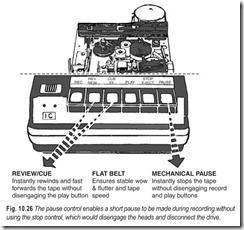
Pause, Stop and Eject : The pause control, used on most cassette recorders, enables a short pause to be made during recording without using the stop control, which would disengage the heads and disengage the drive. Where no pause control is fitted, short stops are inconvenient as they require the manipulation of the play and record keys together to start recording again. Using a pause control eliminates this two finger action, with the advantage that the volume level of recording signal occurring during the pause can be checked. The action of the pause control may be purely mechanical or purely electrical. In the purely mechanical type, the idler wheel is pulled away very slightly from capstan spindle, and the heads are left in contact with the tape, with the capstan spindle still revolving. This ensures a rapid restart when the pause is operated again to press the idler wheel against the capstan, though the acceleration of the tape as the drive is taken up may cause a squeal to be recorded. Some recorders which use capstan motors controlled by low voltage electronic circuits have purely electrical type pause controls which interrupt the supply to the capstan motor and switch off the tape amplifier momentarily as the motor is restarted. Care has to be taken with the electrical type, so that it is not held for long periods. The risk is that the idler wheel pressed in one stationary position against the capstan spindle will develop a flat portion which will from then on cause wow on both recording and playback which do not take place in case of mechanical method.
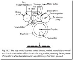
The stop key operates on fast forward, normal play, record or rewind, and its action is to return all functions to the stop position, reversing the sequence of operations which takes place when anyone of the previous keys has been pressed. The piano key controls are made interlocking and spring loaded so that when any key is pressed down, it has to be moved against the force of a spring and once in the operating mode, is locked in position by a ratchet action. Further more once a control, such as fast forward, for example, is operated other controls which carry out different operations cannot be depressed, so making it impossible to operate the keys normally. This stop key does not lock but releases all the ratchets holding any other keys so that when the stop key is operated any other key which has been locked down will spring back. In addition, using the stop key always cuts off the amplifier.
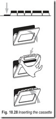
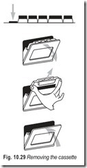
The eject key or catch releases the spring lid which covers or holds the cassette in place. In some models the lid opens and the cassette is sprung away from the driving shafts. In others the cassette is held in grooves in the lid, and pressing the eject key will lift the lid and the cassette with it making cassette removal even simpler.
The eject key may be separate or it may be combined with the stop key, so that a gentle push on the stop key stops operation and a further movement against a stronger spring causes ejection.
MISCELLANEOUS FEATURES
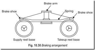
Brakes are usually applied to quickly stop the reels. When the recorder is stopped the reels should stop immediately, otherwise the tape may spill over. In cassette recorders small plastic or metallic bars attached to an arm are used as brakes. When the stop key is operated, the brakes press against both the reels and stop their movement. The brakes are released when any of the keys, other than the stop key, is pressed. One such braking arrangement is shown in Fig. 10.30.
All stereo cassette recorders incorporate some sort of auto stop or warning signal to operate at the end of the tape, or when jamming occurs. They come into action when the takeup spool ceases to turn with the motor still activated. Autostops perform for whole of the usual stop operation, withdrawing the heads and idler and switching the amplifier off.A few recorders incorporate auto reverse switch. When the end of a cassette tape is reached, the signal generated from the detector at the take- up spool causes the tape to reverse and a second set of heads, acting on the other half of the tape width comes into action, so playing the other half of the tape.
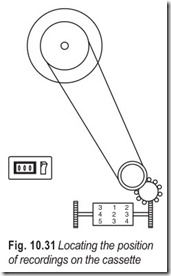
Cheap portable cassette units often use no precise method of locating the position of recording on the cassette, and rely on the crude scaler of tape-reel radius which is engraved on the cassette itself. Such a method is quite unsuitable for serious work and a digital counter of some sort is fitted to all stereo cassette units in the medium to high quality class.
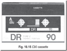
The usual method of operating the counter is by a belt from the takeup shaft, as shown in Fig. 10.31, so that the count rate is rapid at the start of recording a cassette and slow at the end. Because of belt slip the count is not exact, but the position of a recording can usually be found with very little error, often only a second or two out of place. It is useful to know what the maximum count is for a cassette side, a typical value being 680 for a C90 cassette side.
ELECTRONIC CONTROLS
The recording volume controls are more important in use than purely electronic controls. They may take the form of a single volume control together with a balance control, or, more commonly, of separate volume control for two stereo-channels. Some recorders use rotary controls, others use the currently fashionable slider controls, but the aim in each case is to control the amplification of the input signal being recorded, so that the best recording level is achieved. Because of the inevitable differences between the two amplifiers of the stereo pair and differences at the signal source the volume control settings for the two channels may not be identical, but should be close to each other in setting.
One reason for the popularity of slider controls is that they can be set close together so that both L (left) and R (right) volume controls can be altered together, a procedure which is very difficult when separate L and R rotary volume controls are used. When rotary controls are used, a single volume control operating on both channels, together with a balance control to alter the amplification of one channel relative to the other, is preferable.
Many recorders provide separate preamplifiers for the microphone inputs, and in such cases usually provide separate recording volume controls. Where such separate controls are provided, signal mixing of microphones and other inputs is possible.
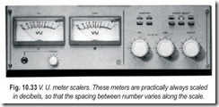
The amount of signal reaching the tape heads is measured by the recording level meters, often called VU (volume unit) meters. The precise quantity which these meters measure depends very much on the design of the recorder, but the principle is always the same : the recording level is adjusted by using the recording volume controls until the maximum level reached by the needles of the meters is to a red line or a ‘0dB’ mark on the meter scale.
Stereo cassette recorders intended for serious use will inevitably incorporate active noise reduction circuits. As far as the user is concerned, the noise reduction switch will be on for all recording from disc or microphone, and all radio recording except where noise reduction has already been carried out on the radio signal. The noise reduction switch will similarly be on for the replay of any recordings made with the same machine, but may be off for other replayed cassettes. When the cassette being replayed has not been recorded using the Dolby process (the only noise reduction process used for pre-recorded cassettes) the noise reduction switch should be off during replay, otherwise there will be a serious loss of high frequencies. Cassettes which have been recorded using the Dolby process should be played back with the Dolby noise reduction switched on.
Some recorders have been manufactured using noise reduction circuits on replay only, these are of the DNL (Dynamic Noise Limiter) type (they are automatically taken out of circuit on recording). A few low and medium quality cassette recorders incorporate switches labelled noise reduction which merely switch in a treble filter, cutting high frequency response. These are not worth using except for recordings of speech, and should normally be switched off.
Input and output adjustment controls are, however, very useful if a cassette deck (not having loudspeaker outputs of its own) is to be matched to any possible amplifier unit. At the input it is usual to have several different inputs of different sensitivity levels. Nevertheless, the tape output from some amplifiers may deliver a signal which is too large for the cassette recorder input, since the volume controls of the cassette recorder are located after the first stage of amplification, and an overload of this first stage cannot be prevented by an adjustment of the recording volume controls. An input adjustment control enables large signals to be reduced in amplitude before reaching the first stage of the recording amplifier.
An output adjustment control can also be useful where the cassette recorder is being used with an amplifier of different design. By adjusting the output control, the replay of the cassette recorder can produce the same volume at the loudspeakers with the same amplifier settings as are used for disc or radio, so avoiding having to make large changes to the setting when switching from one signal source to another.
Most cassette recorders will have a bias amplitude control so that the value of bias can be adjusted for a particular tape. This is not a user control, and is part of the circuit within the case. No attempt must be made to adjust this control except by an experienced electronic engineer suitably equipped with instruments to check the amount of bias at the recording head. Adjustments of Dolby circuits are seldom required except when a change of tape-type is made for some reason or other.
The remaining electrical adjustment is that of supply voltage which will be in the range 110 –115–120 V or 220–230–240 V. This must be set to the correct value for supply in the country concerned. The setting will usually be carried out by the dealer who sells the recorders and will be correct for the country in which it is sold. Adjustment usually requires unplugging the recorder, pulling out the adjustment plug and rotating it until the arrow points to the supply voltage to be used, then pushing in the adjustment plug again. The value of the supply voltage is printed on the electricity meter of the house or apartment.
ERASURE GUARD
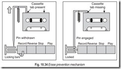
Most recorders now incorporate an erase prevention device which automatically ensures that pre-recorded cassettes cannot be accidentally erased by recording over them. The system uses a mechanical interlock with the record key or button, and is operated by a spring-loaded plunger at the back (opposite the heads) of the cassette holder.
With no cassette in place, the plunger is extended, and the lever connected to it internally locks the record control. When an un-recorded cassette is placed in the holder the back of the cassette presses the plunger in, unlocking the record control. Pre-recorded cassettes have a slot cut in this position at each side (the rear left-hand side, looking at the cassette facing its pressure pad, with either half playing) so that the plunger is not pressed in, and the record control remains locked in the off position.
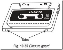
Unrecorded cassettes have a breakable tab at this position, Fig. 10.35, so that when a valuable recording is made it can be protected against accidental erasure by breaking off the tab on the back left-hand corner. If a change of plan requires that this recording is to be erased after all, a piece of sticky tape can be placed over the slot, so that the plunger is pressed in.
TAPE RECORDERS
A vast variety of tape recording devices can be found in today’s market. There are two basic machines; the complete recorder and the deck.
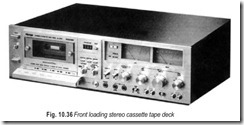
The complete recorders are totally self-contained units Fig. 10.36. They contain the recording, playback and erase mechanisms, the necessary playback amplifiers and loudspeakers. All that is required is a reel, cartridge, or cassette of blank or pre-recorded tape. But you won’t find many amplidecks and high fidelity speakers won’t fit into such small cases.
The second type, the deck, can be subdivided into two classes. The first is the better known one, the record playback type shown in Fig. 10.26. Except for the speakers, these units come equipped with everything you need to record and playback. The other subdivision is the playback only deck or tape player. This type is used only with pre-recorded tapes because it contains no recording mechanism.
The number of operating features change from machine to machine. Some offer sound-on-sound operation. Almost all let you monitor the tape as you record. There are other features too numerous to mention. Just remember, the more options you want the more will it cost you.
TAPE vs DISC
A spool of tape provides an unvarying standard of performance throughout its length. A disc’s performance, in respect of frequency response and distortion falls off to some extent towards the inner grooves. A low overall distortion can be achieved during tape reproduction, and a superior cross talk performance is possible in both the recording and reproduction of tape.
Normally tape has a long life and is not easily damaged. There need be no difference between disc and tape in respect of noise levels; this applies when both are new, but tape may well become noisier than disc after prolonged use.
The handling of tape, a disadvantage for many users, can be avoided by enclosing the spools in cassettes. These are especially useful for tapes which are to remain undisturbed, but the method is of little interest to hobbyists who require easy access to the tape.
Tape is more expensive than disc if high-quality music recording is the aim. For other purposes the cost depends on such factors as tape speed, number of tracks and skill at editing tape. The expense is more apparent if tape reproduction alone, using commercial tape records, is the requirement. Stereo is likely to be more costly than mono.
As far as the music-lover is concerned, discs are the most attractive because of the extensive recorded repertoire. It seems unlikely that tape will ever compete in this respect.
EXERCISES
Descriptive Questions
1. Explain the principle of magnetic recording in reproduction.
2. What are the different methods of erasing the tape?
3. Explain the method of manufacture of anyone of the recording mediums.
4. What is the difference between a record head, a playback head, and an erase head?
5. List the parts of a cassette with the help of a neat diagram.
6. Derive the relation between maximum usable frequency, tape speed and gap width for optimum output.
7. What are the different track configurations for mono and stereo?
8. Explain the mechanical controls of a cassette recorder.
9. Explain the electrical controls of a cassette recorder.
10. How does the erase prevention device operate? Why is it required?
11. What are the different types of tape recorders?
12. What are the advantages and disadvantages of tape over disc?
Multiple Choice Questions
1. All methods of recording and playback rely on a sequence of
(a) reversible processes (b) irreversible processes
2. Tapes with thinner coatings are capable of the
(a) lowest information packing density (b) highest information packing density
3. Metallic thin films
(a) can be controllably produced in much thinner layers
(b) cannot be controllably produced in much thinner layers
4. The size of the gap, particularly for replay
(a) must not be small (b) must be small
5. The use of modern micro-gap heads has now made possible the use of tape speeds as low as
(a) 3¾ ips (b)17/8 ips
(c) 7½
6. It is usual for cassette recorders to have
(a) separate heads for recording and replay
(b) a single head for recording and replay
7. Erasure is carried out with a head with a much
(a) smaller gap (b) wider gap
8. A cassette deck supplies
(a) only motion to the tape (b) only electronics to the tape
(c) motion and electronics to the tape
9. High speeds are used in
(a) domestic cassette recorders (b) good quality studio tape recorders
10. Increasing the tape speed
(a) increases the maximum usable frequency
(b) decreases the maximum usable frequency
11. The width of standard reel tape is
(a) 1 in (b) 1/2 in
(c) 1/4 in
12. The reversing mechanism can be actuated
(a) mechanically (b) electrically
(c) (a) or (b) (d) (a) and (b)
13. Tape transport controls the
(a) movement of the tape (b) handling of the tape
(c) movement and handling of the tape (d) none of the above
14. The maximum count for a C90 cassette side is
(a) 480 (b) 570
(c) 680 (d) 760
Fill in the Blanks
1. All methods of recording and reproduction rely and sequence of………………………………………..
2. The amplitude of voltage across the head coil depends on the ……………………………………….. in the core.
3. The magnetic oxides which are most often used are those of…………………………………………
4. All these oxides are produced in the form of fine …………………………………………
5. A wide variety of magnetic characteristics can be produced by varying the ……………………………………….. of the .
6. The tape passes over the ……………………………………….. before passing over the record/replay head.
7. The tighter you pull the leader the tighter it…………………………………………
8. To obtain longer playing times ……………………………………….. tape must be used.
9. Lower speeds are used for long play in……………………………………….. tape recorders.
10. Higher speeds are used in good quality……………………………………….. cassette recorders.
11. In dual-track stereo recording, both tracks are …………………………………………
12. 4-track recording is simply an extension of ……………………………………….. recording.
13. The record key is an electronic control which is mechanically ……………………………………….. with the other controls.
14. The pause controls enable a……………………………………….. to be made during recording without using the stop control.
15. A……………………………………….. counter of some sort is fitted to all stereo cassette units in the middle to high quality class.
16. The amount of signal reaching the tape heads is measured by……………………………………….. metres .
ANSWERS
Multiple Choice Questions
|
1. (a) |
2. (b) |
3. (a) |
4. (b) |
5. (b) |
6. (b) |
|
7. (b) 13. (c) |
8. (c) 14. (c) |
9. (b) |
10. (a) |
11. (c) |
12. (c) |
Fill in the Blanks
|
1. reversible processes |
2. rate of change of flux |
3. |
iron |
|
4. acicular particles |
5. composition, alloy |
6. |
erase head |
|
7. grasps |
8. thinner |
9. |
domestic |
|
10. professional |
11. recorded simultaneously |
12. |
dual-track |
|
13. interlocked |
14. small pause |
15. |
digital |
|
16. recording level |
