Continuity of Ring Circuit Conductors
( Stage One )
A ring circuit continuity test must be done to ensure that each phase, neutral and protective conductor is continuous and not broken at any point. If any conductor were broken then the load would not be properly shared by the conductors, possibly leaving one conductor overloaded and not adequately protected.
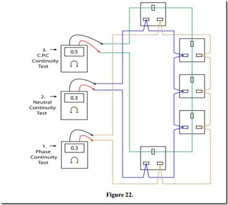
The ring circuit continuity test may be carried out as shown in Figure 22. The six conductors are disconnected from their respective terminals and the continuity of each of the three “rings” is checked in turn.
Readings 1 and 2 should be the same
Example 0.3 Ohms, the resistance of 43 metres of 2.5 mm2 cable.
The relationship between the resistance of 2.5 mm2 cable and 1.5 mm2 cable is 1.67. Reading 3 should be higher by a factor of 1.67.
Example 0.3 x 1.67 = 0.5 Ohms, resistance of 43 metres of 1.5 mm2 cable.
Related posts:
Audio Amplifier Performance:Power Amplifier Classes
POWER ELECTRONICS, RECTIFIERS, AND PULSE-WIDTH MODULATION INVERTERS:PULSE CIRCUITS
Audio Amplifier Performance:AC- and DC-Coupled Amplifiers
Timing relays:Electronic Timers
Electronics Explained – Video Technology
Overload relays:Thermal Overload Relays
Multiple Push-Buttons Stations
The Unijunction Transistor
Induction motor:Relation Between Torque and Rotor Power Factor.
Transformer:Short-Circuit or Impedance Test
GENERATOR COMPONENTS, AUXILIARIES, AND EXCITATION:OTHER COOLING SYSTEMS
ZIG-ZAG AIRGAP LEAKAGE INDUCTANCES
The DC Machine
Motor Calculations part6
