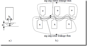
Figure 6.10 Airgap a.) and zig-zag b.) leakage fields
The airgap flux does not reach the other slotted structure (Figure 6.10a) while the zig-zag flux “snakes” out through the teeth around slot openings. In general, they may be treated together either by conformal transformation or by FEM. From conformal transformations, the following approximation is given for the geometric permeance λzs,r [3]
![]() λzs,r ≈ 5+5gK / b4gK / bc c os,ros,r ⋅ 3β +y4 1 <1.0; βy =1 for cage rotors (6.32)
λzs,r ≈ 5+5gK / b4gK / bc c os,ros,r ⋅ 3β +y4 1 <1.0; βy =1 for cage rotors (6.32)
The airgap zig-zag leakage inductance per phase in stator-rotor is
In [4], different formulas are given
Lzls = L1m ⋅12N 2 1− a 1( +a 12)K'( −K’) (6.34) π2p12
s
for the stator, and
Lzlr = L1m ⋅12π2Np1s22 NNsr22 − a 1( +a 12)(K’−K’) (6.35)
for the rotor with K′ = 1/Kc, a = bts,r/τs,r, τs,r = stator (rotor) slot pitch, bts,r–stator (rotor) tooth-top width.
It should be noticed that while expression (6.32) is dependent only on the airgap/slot opening, in (6.34) and (6.35) the airgap enters directly the denominator of L1m (magnetization inductance) and, in general, (6.34) and (6.35) includes the number of slots of stator and rotor, Ns and Nr.
As the term in parenthesis is a very small number an error here will notably “contaminate” the results. On the other hand, iron saturation will influence the zig-zag flux path, but to a much lower extent than the magnetization flux as the airgap is crossed many times (Figure 6.10b). Finally, the influence of chorded coils is not included in (6.34) to (6.35). We suggest the use of an average of the two expressions (6.33) and (6.34 or 6.35).
In Chapter 7 we revisit this subject for heavy currents (at standstill) including the actual saturation in the tooth tops.
Example 6.2. Zig-zag leakage inductance
For the machine in Example 6.1, with g = 0.5⋅10-3m, bos = 6g, bor = 3g, Kc = 1.32, L1m = 0.1711H, p1 = 2, Ns = 36 stator slots, Nr = 30 rotor slots, stator bore Di = 0.102m, By = y/τ = 8/9 (chorded coils), and W1 = 300 turns/phase, let us calculate the zig-zag leakage inductance both from (6.32 – 6.33) and (6.34 – 6.35).
Solution. Let us prepare first the values of K′ = 1/Kc = 1/1.32 = 0.7575.
1− b NπosDi s = −1 6 0.5⋅ π⋅0.⋅10102⋅36 = 0.6628
1− π(Db Nori r ) = −1 3 0.5
= −2g ⋅ π⋅⋅0.10101−3 ⋅30 = 0.858
(6.37)
−3
The zig-zag inductances per phase Lzls,r are calculated from (6.33).
2 1.⋅ 256 10⋅ 2 3−−⋅6 ⋅3002 ⋅0.12 ⋅0.187 = 8.455 10⋅ −4 H (6.40)
Lzls,r = 2 1.⋅ 256 10⋅ 2 3⋅6 ⋅3002 ⋅0.12 ⋅0.101= 4.566 10⋅ −4 H
Now from (6.34) – (6.35),
Lzlr = 0.1711⋅12 36⋅ 2 3630 2 − 0.858(1+2 0.0.⋅8587575)(1−0.7575) = (6.42) π2 22
= 3.723 10⋅ −4 H
All values are small in comparision to L1m = 1711⋅10-4 H, but there are notable differences between the two methods. In addition it may be inferred that the zig-zag flux leakage also includes the differential leakage flux.
END-CONNECTION LEAKAGE INDUCTANCE
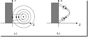
As seen in Figure 6.11, the three-dimensional character of end connection field makes the computation of its magnetic energy and its leakage inductance per phase a formidable task.
Analytical field solutions need bold simplifications. [5]. Biot-Savart inductance formula [6] and 3D FEM have all been also tried for particular cases.
Some widely used expressions for the end connection geometrical permeances are as follows:
• Single-layer windings (with end turns in two “stores”).
![]() λes,r = 0.67⋅ qLs,re (les,r −0.64τ) (6.43)
λes,r = 0.67⋅ qLs,re (les,r −0.64τ) (6.43)
• Single-layer windings (with end connections in three “stores”).
![]() λes,r = 0.47⋅ qs,r (les,r −0.64τ) (6.44)
λes,r = 0.47⋅ qs,r (les,r −0.64τ) (6.44)
Le
• Double-layer (or single-layer) chain windings.
![]() λes,r = 0.34⋅ qs,r (les,r −0.64y) (6.45)
λes,r = 0.34⋅ qs,r (les,r −0.64y) (6.45)
Le end connection length per motor side.
For cage rotors,
•
With end rings attached to the rotor stack.
λei ≈ 2 3e⋅ ⋅DirπNpr1 l 4.7g aD+ ir2b
4N L sinr 2 (6.46)
•
With end rings distanced from the rotor st.ck:
SKEWING LEAKAGE INDUCTANCE
In Chapter 4 on windings, we did introduce the concept of skewing (uncompensated) rotor mmf, variable along axial length, which acts along the main flux path and produces a flux which may be considered of leakage character. Its magnetic energy in the airgap may be used to calculate the equivalent inductance.
This skewing inductance depends on the local level of saturation of rotor and stator teeth and cores, and acts simultaneously with the magnetization flux, which is phase shifted with an angle dependent on axial position and slip. We will revisit this complex problem in Chapter 8. In a first approximation, we can make use of the skewing factor Kskew and define Lskew,r as
Lskew,r = (1− K2skew )L1m (6.48)
Kskew = sinααskewskew ; αskew = cτ π2 (6.49)
As this inductance “does not act” when the rotor current is zero, we feel it should all be added to the rotor.
Finally, the total leakage inductance of stator (rotor) is:
Lls = Ldls + Lzls + Lsls + Lels = 2µ0 W Lpq1 e ∑λsi
(6.50)
Llr = Ldlr + Lzlr + Lslr + Lelr + Lskew,r
(6.51)
Although we discussed rotor leakage inductance as if basically reduced to the stator, this operation is due later in this chapter.
6.9. ROTOR BAR AND END RING EQUIVALENT LEAKAGE INDUCTANCE
The differential leakage Ldlr, zig-zag leakage Lzl,r and Lskew,r in (6.51) are already considered in stator terms (reduced to the stator). However, the terms Lslr and Lelr related to rotor slots (bar) leakage and end connection (end ring) leakage are not clarified enough.
To do so, we use the equivalent bar (slot) leakage inductance expression
Lbe,
Lbe = Lb + 2Li (6.52) where Lb is the slot (bar) leakage inductance and Li is the end ring (end
connection) segment leakage inductance (Figure 6.13) Using (6.18) for one slot with nc = 1 conductors yields:
Lb = µ0Lbλb (6.53) Lei = µ0Liλer (6.54) where λb is the slot geometrical permeance, for a single layer in slot as calculated in paragraphs 6.4 and 6.5 for various slot shapes and λer is the geometrical permeance of end ring segment as calculated in (6.46) and (6.47). Now all it remains to obtain Lslr and Lelr in (6.51), is to reduce Lbe in (6.52) to the stator. This will be done in paragraph 6.13.
6.10. BASIC PHASE RESISTANCE
The stator resistance Rs is plainly
Rs = ρCo cl Waa A1cos KR (6.55) where ρCo is copper resistivity (ρCo = 1.8⋅10-8Ωm at 250C), lc the turn length:
lc = 2Le + 2b + 2lec (6.56) b–axial length of coil outside the core per coil side; lec–end connection length per stack side, Le–stack length; Acos–actual conductor area, a–number of current paths, Wa–number of turns per path. With a = 1, Wa = W1 turns/phase. KR is the ratio between the a.c. and d.c. resistance of the phase resistance.
KR = RRsdcsac (6.57)
For 50 Hz in low and medium power motors, the conductor size is small with respect to the field penetration depth δCo in it.
![]() ρCo < dCo (6.58) δCo = µ π0 f1
ρCo < dCo (6.58) δCo = µ π0 f1
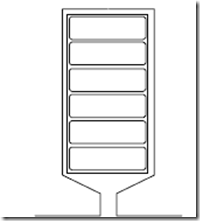
In other words, the skin effect is negligible. However, in high frequency (speed) special IMs, this effect may be considerable unless many thin conductors are transposed (as in litz wire). On the other hand, in large power motors, there are large cross sections (even above 60 mm2) where a few elementary conductors are connected in parallel, even transposed in the end connection zone, to reduce the skin effect (Figure 6.12). For KR expressions, check Chapter 9. For wound rotors, (6.55) is valid.
λei ≈ 2 3⋅ ⋅Di πp1 l 4.7g 2(aD+i b)
4N L sinr e 2 Nr
(6.47)
with qs,r–slots/pole/phase in the stator/rotor, Le–stack length, y–coil throw, les,r– with a and b the ring axial and radial dimensions, and Dir the average end ring diameter.
THE CAGE ROTOR RESISTANCE
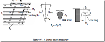
The rotor cage geometry is shown in Figure 6.13.
Let us denote by Rb the bar resistance and by Ri the ring segment resistance:
R b = ρb Albb ; Ri = ρi Alii ; Ai = a b⋅ (6.59)
As the emf in rotor bars is basically sinusoidal, the phase shift αer between neighbouring bars emf is
The current in a bar, Ibi, is the difference between currents in neighboring ring segments Iii and Iii+1 (Figure 6.13).
Ibi = Iii+1 − Iii = 2I sini (αer / 2) (6.61)
The bar and ring segments may be lumped into an equivalent bar with a resistance Rbe.
R beIb2 = R Ib b2 + 2R Ii i2 (6.62)
With (6.61), Equation (6.62), leads to
Rbe = Rb + Riπp1 (6.63) 2sin2 Nr
When the number of rotor slot/pole pair is small or fractionary (6.49) becomes less reliable.
Example 6.3. Bar and ring resistance
For Nr = 30 slots per rotor 2p1 = 4, a bar current Ib = 1000 A with a current density jcob = 6 A/mm2 in the bar and jcoi = 5 A/mm2 in the end ring, the average ring diameter Dir = 0.15 m, lb = 0.14 m, let us calculate the bar, ring cross section, the end ring current, and bar and equivalent bar resistance.
Solution
The bar cross-section Ab is
Ab = jIcobb =1000/6 =166mm2 (6.64)


