FAULT-FINDING IN VIDEO SIGNAL CIRCUITS
With a reasonable working knowledge of circuit principles, a service manual and fairly simple test equipment, diagnosis of faults in the signal processing stages is not difficult. The first thing to establish is whether the fault is present during record, playback or both. To check for record faults the suspect tape is played back in a known-good machine of the same format; to check for replay faults a known- good tape containing test patterns and colour bars on vision, and a 1 kHz tone on sound, is ideal. This test tape need not be the very expensive alignment (interchange) tape produced by videorecorder manufacturers as a standard reference; to avoid wearing it unduly, it should be reserved for interchange and alignment testing, and used as seldom as possible. The test tape can be recorded on a new well- aligned machine, and its characteristics checked against those of the precision alignment tape in the same machine.
Record luminance faults
Once it has been established that the input signal is of good qual- ity, any shortcoming in record performance will be due to faults or misalignment in the record section. A noisy or ‘streaky’ record- ing suggests head wear; if the same effect is present after cleaning the video heads (see Chapter 18) the luminance writing current should be checked. Streaking or noise at vertical edges of picture features can also be due to worn heads, but may possibly have its origin in a malfunctioning f.m. modulator (check frequency and deviation with a digital frequency counter) or too high an operating level of the white clipper. Incorrect modulator frequencies can also lead to a change in luminance levels generally or a ‘gamma shift’ in which one end of the grey-scale becomes stretched or compressed.
Maladjustment or faults in the clippers will also affect the extremes of the composite luminance signal: too low a white clip level will ‘flatten off’ highlights, and wrong dark-clip level foreshortens the sync pulses. A lack of detail in the recording suggests insufficient pre-emphasis. Further possibilities in the luminance record channel are too high a writing current, flattening off large chroma signal excursions; and faulty bandpass filters, allowing the modulator to overdeviate. This can create beat pat- terns with the chroma signal, especially at sharp transitions and in highly detailed areas of the picture.
Playback luminance faults
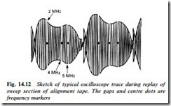
Perhaps the most common replay fault is that of a snowy, streaky picture with much dropout. If the video heads are clean, and confirmation of a low f.m. carrier level is made, head wear is almost always responsible. Any form of 25 Hz flicker in the picture means that the two head signals are unbalanced in some way: ‘noise’ flicker implicates head wear in one head or malfunction of its preamplifier channel; flicker of high- or low-frequency gratings in the picture should direct attention to the affected preamp. These can only be checked properly during replay of the ‘sweep’ section of a factory- made alignment tape whose signal, over one TV field-scan period (one head sweep), ranges through all those normally handled by the video heads – a typical oscilloscope trace of a sweep-tape replay is shown in Fig. 14.12, and the preamps’ frequency response is designed to achieve the pattern shown here.
Causes of poor resolution downstream of the head preamps can be: a maladjusted or faulty noise canceller; a defunct picture- sharpening circuit; or a faulty bandpass filter. Such things can be tracked down by oscilloscope signal tracing, with careful examination of test-pattern ‘grating’ amplitudes or rise-fall times of transients in stairstep or colour-bar waveforms. Spurious beat pat- terns on the monochrome picture, where recording problems are not responsible, will generally be due to failure of bandpass filters, or more commonly to vestiges of the f.m. carrier itself appearing on the output signal. Sometimes a faulty demodulator is responsible, but imbalance in limiters, demodulator etc. is a more
likely cause; poor balancing is indicated by ‘grass’ on unmodu- lated sections of the waveform such as sync pulses, porches and the ‘tread’ sections of stairstep signals.
Chroma record faults
Because most of the colour-under circuitry is common to record and replay, there is little likelihood of a chroma-record fault which does not upset colour on playback. Cases of no- or poor colour record, then, can generally only arise from: failure of either the input (4.43 MHz) or colour-under output (620–680 etc. kHz) bandpass filters or the signal routeing to and from them, e.g. record chroma add stage; failure of the 25 Hz flip-flop pulse (derived from incom- ing field sync) to the record phase (frequency) shifting block; or problems in the record/playback switching circuits.
Chroma replay faults
Most replay faults affect record too, but are easier to diagnose if dealt with in replay mode, where progress can be monitored on the TV screen and a convenient source of test signal is a known good tape containing stationary colour bars. Some important points to remember are (a) weak colour-under signals will, due to the action of the a.c.c. circuits, give rise to noisy colour signals rather than desaturation – the effect is of ‘cotton-wool’ in highly saturated parts of the picture, colour-confetti elsewhere; (b) most colournder problems invoke the action of a colour-killer circuit, which shuts down the chroma channel to render diagnosis more difficult; this particularly applies to frequency or phase errors, and the killer action cannot usually be easily overriden, necessitating oscilloscope investigation of the killer trigger circuits; and (c) the readout of a frequency counter or timer can be misleading in some sections of the circuit because it usually counts zero-crossings over a sampling period rather than dominant frequency. Thus erroneous readings would be given at the phase rotated 625 kHz input to balanced modulator 1 in Figs 14.6 and 14.8, unless the phase rotator is stopped by holding the flip-flop input high to simulate constant-phase head A condition. Outputs from mixers and modulators contain many frequencies and will again give misleading readings from a digital counter.
A 25 Hz flicker in the coloured parts of the picture will almost certainly be due to a problem in one head or its associated circuit; if the luminance signal is unaffected, poor l.f. response is the obvious
possibility. Complete loss of colour on every other field, if colourunder signals are emerging from the head preamplifiers, suggests a problem in the frequency/phase rotational circuit; it is always within an IC, but check pulse feeds and peripheral components before condemning the chip.
Poor colour lock, with horizontal bands of colour flashing on and off, or floating vertically on the picture, indicates that one of the colour phase correction loops (a.f.c., based on off-tape line sync, or a.p.c., based on a local 4.43 MHz crystal) has failed. A first step here should be a frequency-counter check of the free-running frequencies of the crystal(s) used in the colour replay circuits. Most colour phase and frequency faults, however, are not visible on the TV or monitor screen because of the action of one or more colour killer circuits either in the videorecorder or in the monitor TV.
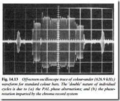
No colour is the most common manifestation of chroma circuit faults. A quick first check is to ensure that the crystal oscillator(s) is running and producing the correct frequency. Many no-colour faults are due to an absence of an essential ancillary pulse feed; a check on head flip-flop pulses into the chroma frequency/phase rotator circuit, and for the presence of line-rate triggering and burst-gating pulses will often expedite the diagnosis. If all pulses are present and correct the oscilloscope must be used to trace the chroma signal itself. In colour-under form (i.e. based on 600–700 kHz) the standard colour bar waveform looks like the ’scope trace of Fig. 14.13. It should appear in this form as far as the input of the up-converting modulator or mixer, i.e. balanced modulator 2 in Fig. 14.8. If so, and no up-converted colour output appears from the mixer, it is likely (assuming that the output filter has signal-continuity) that one of the ‘local’ inputs to the mixers is faulty or missing.
Each of the two mixer/modulators has two inputs, and all of these should be checked in turn with the ’scope. Most of the colour-under circuitry is contained in a single IC and fault-finding here is largely confined to seeing that it has correct inputs, pulse-feeds and supply- line voltages; if all these, and such peripheral components as decoupling capacitors are correct, the IC must be replaced. If there is no colour on replay of video recordings made elsewhere, but the VCR’s own new recordings play back with colour, the likelihood is that the video head drum has been fitted 180° out of phase on its shaft/table during service. Under these circumstances new recordings made in the afflicted machine will give a black-and-white picture in replay on another VCR.
Occasionally coloured picture areas may be afflicted by a swirly or herringbone pattern which disappears when the colour is turned
down. A local m.f. (medium-wave) radio transmitter may be responsible for breakthrough into the colour-under circuits, in which case a filter in the UHF aerial lead or additional head/circuit shield- ing may effect a cure. Other possible causes are faulty bandpass filters in the chroma or luminance sections, or a high degree of luminance (f.m.) carrier leak, whose frequency is near 4.43 MHz, and whose level will be excessive if the luminance circuits are not balanced at f.m. carrier frequency.

