Extra high tension
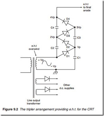
A final anode voltage known as the extra high tension (e.h.t.) in the region of 15–30 kV is required by tube to attract and accelerate the electrons. This e.h.t. is produced by a voltage multiplier network known as the tripler (Figure 9.2). The a.c. voltage input is obtained from an overwind
on the line output transformer. C1/D1 act as a clamper which charges C1 to the peak of the input voltage, Vp. This is then applied to the second clamping circuit consisting of D2 and C2 charging C2 to 2 X Vp and so. The elements of the tripler are contained in a single well isolated pack- age or capsule known as the Tripler.
Monochrome tube
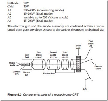
The monochrome display tube consists of a single electron gun, an anode assembly acting as the electron lens and a viewing surface. The beam passes through a 4-anode assembly (Figure 9.3) which provides accelera- tion (A1), electrostatic focusing (A2/A3) and final e.h.t. anode (A4). As well as the grid potential the emission of electrons is also dependent upon the potential between the cathode and the first anode. An increase in the potential between these two electrodes causes more electrons to be emit- ted and vice versa. The actual tube voltages depends on the size of the tube and its design, however the following are typical voltages for a monochrome receiver tube:
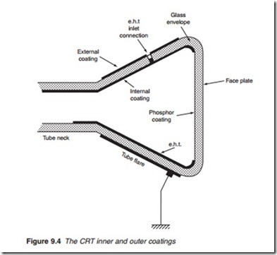
pin connections at the back of the neck of the tube with the exception of the final anode which is accessed along the tube flare. The inside and out- side of the tube flare are coated with a layer of graphite known as aquadag coating (Figure 9.4). The outer coating is connected to chassis and the inner coating is connected to the e.h.t. The glass separation between them forms a reservoir capacitor for the e.h.t supply. This is why it is important that this capacitance is fully discharged before handling the tube other- wise a very violent shock may be experienced.
In order to produce a display the electron beam is deflected in the hor- izontal and vertical directions. Electromagnetic deflection is employed using two sets of coils (line and field) known as scan coils placed along the neck of the tube.
The tube’s angle of deflection forms an important specification of the CRT. It refers to the angle through which the beam is deflected as it goes across the screen. The most common deflection angle is 90º although 100º and 110º are widely used for large tube displays. The deflection angle depends on the strength of the magnetic field created by the scan coils, the
speed of the electron beam which is a function of the e.h.t. and the diameter of the neck of the tube. A narrow neck allows the scan coils to operate in close proximity to the beam and hence exercise greater influence upon it.
Screen size
Another tube specification is the tube size which refers to the diagonal measurement from the lower corner to the opposite upper corner of the screen given in inches or centimetres as illustrated in Figure 9.5. However, the tube size does not translate into the actual display or visible screen size. The television tube is generally partially covered by the external cas- ing of the screen. In addition, the tube cannot project an image to the edges of the full tube size. For instance, a 28 inch (71 cm) tube has a visible screen of 26 inch (66 cm). The precise dimensions of the screen depends on the aspect ratio, e.g. 4:3 or 16:9 (widescreen). The power required by the scan coils is a function of the size and geometry of the tube (screen size and neck diameter) as well as the deflection angle and the e.h.t. applied to the final anode.


