FREEZE-FRAME FACILITY
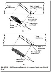
The concept of freeze-frame is a simple one: stop the tape transport and permit the spinning video heads to continually scan the now- stationary tape track, reading out continuously the same TV field complete with sync pulses. TV field scan continues to be triggered by the regularly repeated 20 ms-interval sync pulses, and the reproduced picture should be a frozen image. In practice a problem arises: the angle of the video tracks laid down during record is not the same as that of the guide rabbet around the lower head drum – it is modified, made more shallow. During normal-speed replay the moving tape ensures that the head/track alignment is correct. When the tape is stopped, however, the effective head-scanning angle reverts to that of the guide rabbet. As Fig. 13.10(a) shows, the disagreement between head scan and tape track angles gives rise to mistracking and consequent noise bars at one or more points in the field scan. If the mistracking is bad at the beginning of head-scan the field sync pulses will be missing or distorted, leading to field tripping and picture rolling on the monitor screen. To overcome this problem wider heads are needed to scan a broad enough path to pick up sufficient f.m. carrier throughout their sweep of the tape, Fig. 13.10(b). Some vid- eorecorders are fitted with wide auxiliary heads on the drum to be switched in during still-frame and other ‘trick’ modes.
A common approach to the problem of achieving noise-free still frame is to provide two wide heads to ensure that each head sees enough of its own (azimuth-tilted) track on freeze-frame operation
to render a usable f.m. replay signal. Typically head A may be 59 microns wide, and head B 79 microns wide. Provided the tape is stopped at the right point (head A crossing symmetrically over an ‘A’ track) the still picture reproduced is noise-free. The stopping-point of the tape does not occur at random when the pause or still-frame mode is called up; the capstan motor comes under the influence of a circuit which examines the off-tape video signal for mistracking noise,
and is braked at just the correct point to render a noise-free picture. The exact nature of this capstan-halt procedure varies with the design and vintage of the machine: in early types several ‘shunts’ were involved during which the noise bar was shuttled out of the picture, whereas later machines with more advanced circuitry achieve the cor- rect stop-point instantaneously.
The extra-wide heads are used during record modes in machines where only two heads are provided for standard-play use. Since their bottom edges are on the same reference plane, however, each lays down its recorded video track 49 microns (standard VHS track- width) above the bottom edge of its predecessor’s track, and for each head the excess track width is erased by the recording action of the next head sweep, a process called overwriting.
Artificial vertical syncs
It can happen that due to imperfect tracking the field sync pulse in still-frame mode is noisy or distorted. Even if not, the fact that both heads now have exactly the same path and starting point for their sweeps means that (due to the offset starting points of adjacent slant- ing video tracks) there will be a timing error of 1^ TV lines between the field sync pulses coming from alternate head sweeps. This would badly upset field triggering in the monitor, and cause vertical judder in the reproduced still frame. To prevent that, a circuit called a VD (Vertical Drive) synthesiser is added; it generates and inserts into the output waveform a specially made vertical sync pulse whose timing is governed by a user-control with which vertical judder can be eliminated on still-frame: very often the tracking-control keys are switched to this function in still-frame mode.
Repeat-field still frame
The freeze-pictures described above can eliminate still-frame problems due to the mechanics of the machine itself, but judder and blurring of the reproduced ‘frozen’ picture can still occur on fast- moving picture objects. If anything in the scene moves significantly during the 20 ms field period the alternately reproduced interlaced fields will be quite different and their combination into a single frame unsuccessful; typical of this is a wobble effect on a player – or on the ball – in a fast-moving sport shot.
Fast-action wobble on still-frame can be overcome by reading out a single video track continuously, presenting it twice (with suitable half-line offset of the field sync pulse) as the two fields of a single frame. While some vertical definition is lost as a result, the still picture is perfectly still. The video head configuration to achieve it is relatively simple: One of the two head chips has two gaps with opposing azimuth angles, each with its own winding. If the chosen head is designated ‘A’ its auxiliary winding and gap (called head B2) will have the same azimuth angle as the ‘B’ head on the opposite side of the drum. The auxiliary head (wide type) is not used during record, being switched in only on still-frame reproduction.
An alternative and earlier arrangement is the provision of two completely separate wide heads on the drum, mounted 90° away from the standard heads A and B. Both these auxiliary heads have B-type azimuth, and come into play only on still-frame and double-speed replay modes.
The use of digital field stores in consumer electronics led to electronic still-frame. Here a complete field of video information is captured before the tape stops, then digitised in 6-bit or 8-bit form for storage in a fast, high-capacity DRAM. The captured field is continually and repeatedly read out, according to newly generated sync pulse trains, to give a noise- and jitter-free still picture image.
A later approach to the challenge of producing good still-frame pictures is the dynamic drum system described in Chapter 15 and Figs 15.6 and 15.7.
