TILT SERVO
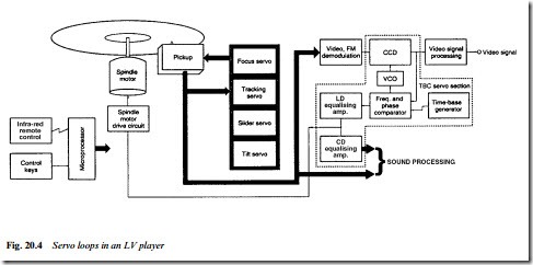
In normal operation the light beam is at precisely 90° to the disc surface. If the disc is warped the beam strikes it at some other angle, making for poor readout and consequent crosstalk from an adjacent pit-track. To prevent this a tilt servo can be incorporated to continually adjust the beam angle within the range ±2° and thus maintain its perpendicularity to the disc face. The pick-up assembly incorporates a tilt sensor in which a pair of photodiodes receive reflected light ‘sidebeams’ from an LED. The difference in their cur- rents indicates the degree of tilt present, and is made to drive a tilt motor to compensate. A block diagram of the servo systems of a Laserdisc player is given in Fig. 20.4.
SYSCON, FIELD AND CHAPTER INDEXING
Laservision players, like videorecorders, have a comprehensive syscon section governed by a microprocessor containing RAM and ROM. As in tape machines it governs motor running, interpretation of user commands, safety functions, go-to, search and other trick modes. There are, however, several differences between videorecorder and Laserdisc syscons; the most fundamental being that the disc-syscon receives commands and feedback from the disc programme itself. These are in the form of digital codes, very similar to Teletext signals, inserted in some of the TV lines during the field blanking interval. The lines used are 17, 18, 280 and 281, and their signals (extracted from the replay signal circuits and decoded) have the following functions:
1. Lead in: the first 1000 or so tracks contain code 88FFFF to send the slide at 9× speed to the programme start point
2. Lead-out: the last 600 or more tracks contain code 80EEEE to return the slide to the beginning at 75× speed; during this time the signal circuits are muted.
The codes used during the programme itself depend on disc type. For CAV discs:
3. Picture code: a unique number for each individual picture in a programme, running from 1 upwards; about 45 000 individu- ally addressable pictures is the capacity of a CAV disc. The picture number can be displayed in one corner of the TV screen if required, and memorised for subsequent quick access
4. Chapter code: a chapter number which identifies each segment of a programme; used for chapter search functions. Again the chapter number can be displayed on the TV screen at will. For CLV discs the range of functions is more limited, and the control data here is:
5. Code 87FFFF, corresponding to ‘normal play’ in which the special operation modes described above are disabled; and
6. Time code: a running count similar to the tape counter in a video- recorder. It provides a readout of elapsed disc time in minutes and seconds and can be displayed on the screen at will; and used with a go-to function, whereby the required time point is programmed by the user into RAM in the control microproces- sor for automatic finding

