TV SIGNAL PROCESSING
In TV receivers and monitors the final recipient of the video signal is the picture tube, be it a monochrome or colour type. The tube requires a modulating voltage between its grid and cathode; normally the grid is clamped at some fixed potential and the modulating signal applied to the cathode. In a monochrome system that signal will be the video waveform in inverted form – to produce white the cathode must be driven down towards grid potential. In a colour-tube the grid is common to all three beams (Chapter 5) and the cathodes are fed by RGB video signals, negative-going for white.
TUBE-DRIVE AMPLIFIERS
Large picture tubes require a peak to peak voltage drive approach- ing 100 V to produce a bright contrasted picture, small monochrome tubes 50–70 V. It is the job of the final video amplifier to provide this drive, and for full detail in the picture its frequency response should extend from d.c. to beyond 5 MHz. For data-monitors, and for sharp display of teletext and computer-generated characters and graphics, the video amplifier response must be better – to 10 MHz and more. The stray capacitance of the video amplifier’s load, represented by the tube cathode, base connections, transistor heat sink and associated wiring can exceed 10 pF, whose reactance at 5.5 MHz is 3 kΩ, and at 12 MHz is less than 1.5 kΩ. To avoid curtailment of h.f. response, then, the final video amplifier must have a very low output impedance to ‘swamp’ the capacitance of the load. Class A amplifiers have relatively high output impedance with practical values of collector load resistance and operating current, though they are used in domestic monochrome TVs and basic colour sets, where h.f. response is enhanced by the use of peaking coils in the collector circuit; and/or frequency-selective negative feedback by virtue of a suitable bypass capacitor across the emitter resistor. For more exacting requirements class AB video amplifiers are usually specified.
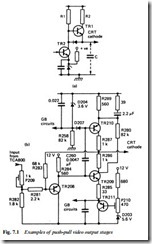
Fig. 7.1(a) shows the form of a commonly used variant with two npn transistors. TR2 functions as a class A amplifier with R1 as col- lector load. When the transistor is being driven on (i.e. picture brightening) its low impedance to ground rapidly discharges stray capacitance C. For a picture transition towards black, however, TR2
c-e impedance rises, and stray C can only slowly charge via load R1, resulting in a blurred trailing edge on the picture feature. TR1 remedies the situation by conducting at this time via low-value resistor R2 to provide a shunt across R1 and a quick charge path for C. Fig. 7.1(b) gives a full circuit of one of the three primary-colour output stages in a commercial colour TV. TR208 forms an emitter- follower driver stage whose output is developed across R284. TR209 is the basic video amplifier with collector load consisting of the paral- lel combination R280 and TR210. The current flowing through this circuit remains fairly constant. HF signals are applied to TR210 base via C260. D204 and R258 provide bias for pnp TR210, and D207 offers a degree of d.c. restoration. R289 and R285 equalise the cur- rent swings in the two transistors. R286 and R287 limit peak cur- rent, and hence power dissipation – and provide some protection in the event of short-circuits. The stage is stabilised by d.c. feedback via R283 to TR208 base, and the values of R281, 282 and 283 are chosen so that no current flows through P209 at black level.
The potentiometers P209 and 210 represent the difference between a video output stage in a good quality monochrome receiver or monitor, and one of the three matched RGB amplifiers driving the tube of a colour set. In the latter case it is necessary to equalise the light output of the three colour phosphors near black level by background controls – P210 and its equivalents in the other stages – which set the tube cathode voltages at black level; and also to provide separate contrast (drive) controls for each primary colour. These grey-scale tracking controls are adjusted for true white (illuminant D) from the colour-tube display at all levels of video drive. The background controls are trimmed for neutral colours in the lowlights and then the drive controls (P209 in Fig. 7.1 and its equivalents) for true white in the highlight picture areas. Only when the grey-scale is correct will true colour reproduction be achieved. In sets incorporating auto-grey- scale tracking (see later, this chapter) the need for the background controls is removed.
