The IF response curve
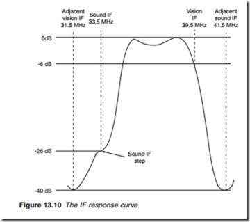
Apart from providing sufficient IF amplification to drive the detector, the IF stage is required to shape the frequency response of the received signal to that shown in Figure 13.10. The IF response curve has four purposes:
1. To reject the vision IF of the adjacent higher channel. The adjacent vision IF falls 8 MHz below the vision IF at 39.5 – 8 = 31.5 MHz.
2. To reject the sound IF of the adjacent lower channel. The adjacent sound IF falls 8 MHz above the sound inter-carrier at 33.5 + 8 = 41.5 MHz.
3. To provide 26 dB attenuation at 33.5 MHz. This is necessary to prevent any interference caused by a beat between the sound and vision IFs. A small step or ledge is provided as shown to accommodate the FM devi- ation of the sound inter-carrier. The FM step prevents amplitude mod- ulation of the sound carrier; otherwise it would be detected by the vision demodulator, causing a pattern to appear on the screen and a buzz on the sound, a symptom known as sound on vision.
4. To provide a steady fall in amplitude from 38 to 41 MHz at the vision IF end. This is necessary because the vestigial sideband transmission gives increased emphasis to these frequencies.
These four functions become very critical in colour TV reception. The 4.43 MHz chrominance sub-carrier falls at the higher end of the video spectrum, and when this is converted to an IF it becomes 39.5 – 4.43 = 35.07 MHz, only 1.57 MHz away from the 33.5 MHz sound IF. It follows that, in order to retain the full chrominance information and its correct relationship to the luminance information, the response curve on the one hand must not be allowed to fall too early at this end, thus restricting the chrominance information, and on the other hand must provide sufficient rejection of the sound IF. Failure to do this produces cross-modulation between the 4.43 MHz chrominance sub-carrier and the 6 MHz soundinter-carrier. This cross-modulation appears as a 1.57 MHz (6.00 – 4.43) pattern on the screen, known as herring-bone pattern.
The vision detector
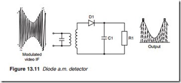
In the amplitude-modulated waveform, the information is contained in the change of amplitude of the peak of the carrier waveform. By joining the tips of the carrier, an envelope is obtained which represents the origi- nal modulating information. The purpose of an a.m. demodulator is there- fore simply to retrieve that envelope while removing the high-frequency carrier wave. This may be carried out by the simple rectifier diode detec- tor with a smoothing low pass filter shown in Figure 13.11. For adequate reproduction of the video information, the time constant of the detector C1Rl must be shorter than the period of one cycle of the highest video frequency, 5.5 MHz, and longer than the duration of one cycle of the 39.5 MHz IF. It follows that the time constant has to be somewhere in between 1/5.5 = 0.18 J.s and 1/39.5 = 0.025 J.s. For this reason, 0.1 J.s is nor- mally aimed for. A time constant longer than 0.1 J.s would reduce the high- frequency response of the detector. The output which is the charge across C1
is then no longer able to follow the fast changes in brightness which are rep- resented by high video frequencies. A very short time constant, on the other hand, would retain a high proportion of the IF in the form of a ripple.

