The three-PBS LCoS system
The main components of a three-PBS LCoS-based system are illustrated in Figure 19.12. Light from the light source assembly is separated into RGB using dichroic filters and mirrors in the normal way. The three beams are directed towards the three PBSs by several fold mirrors. Before hitting the PBSs, the light beams are polarised by sheet polarisers in order to improve contrast. Each PBS reflects S-polarised light towards its respective panel. The light enters the liquid crystal pixel through the glass cover and is reflected back to the liquid crystal by the mirror surface. If an electricfield is applied to the liquid crystal by a video signal (the ‘on’ state), the double pass through the liquid crystal rotates the S-polarised light intoP-polarised light which can efficiently pass through the PBS and proceed towards the colour combiner. With no voltage applied (‘off’ state), the light polarisation is not rotated and the S-polarised light is deflected back on towards the lamp. Light from the red, green and blue channels is recombined in the x-cube dichroic beam combiner to be projected on a screen via a telecentric projection lens.
ColorSelectTM LCoS-based systems
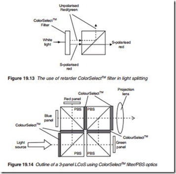
Polarised beam splitters may be used as an alternative to dichroic mirrors to split light into its three primary colours. This is accomplished by polarisa- tion coding. For instance, take the case of S-polarised red and P-polarised green/blue colours. When fed into a PBS illumination port, the PBS will split them with red appearing on one port and green/blue on a separate port as
shown in Figure 19.13. Colour polarisation is carried out by a ColorSelectTM retarder filter. The red and green may be further split using a second ColorSelectTM filter/PBS. The ColorSelectTM filter is a multi-layer laminate of retardation films that converts one spectral band, e.g. a primary colour to an orthogonal polarisation while leaving the remaining spectrum (green/blue) unaffected as illustrated in Figure 19.13. The outline of a complete system is illustrated in Figure 19.14. Retarders are used at PBS ports other than the illumination port in order to re-polarise or de-polarise the exiting light.
