Enhanced FEC
One of the main problems facing mobile TV transmission is the low signal- to-nose, S/N (or carrier-to-noise, C/N) ratio and the effect on the received radio frequencies caused by the Doppler effect. The Doppler effect, named after Christian Doppler, is the apparent change in frequency of a wave received by a handset that is moving relative to the transmitting source. This is the same effect on sound waves when the source, e.g. an ambulance
On the Data Link layer that precedes the Physical layer, an additional stage of forward error correction (FEC) is added. This technique, called MPE-FEC, is the second main innovation of DVB-H besides the time slic- ing. MPE-FEC complements the physical layer FEC of the underlying DVB-T standard. It is intended to reduce the S/N requirements for recep- tion by a handheld device by as much as 7 dB.
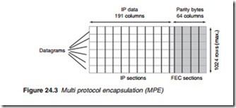
The MPE-FEC encoder creates a specific frame structure, incorporating the incoming data of the DVB-H codec. The FEC frame consists of a max- imum of 1024 rows and a constant number of 255 columns (Figure 24.3). The frame is separated into two parts, the application data table (191 columns) and the RS parity data table (64 columns). The application data table is filled with the IP packets of the service being received. After apply- ing the RS error to the coding, the IP packets are read out of the applica- tion data table and are encapsulated in IP sections. This is followed by the
parity data which are read out of the RS data table column-by-column and are encapsulated in separate FEC sections. Each MPE-FEC frame is con- tained within one time-slicing burst.
By adding parity information calculated from the datagrams and send- ing this parity data in separate MPE-FEC sections, error-free datagrams can be output after MPE-FEC decoding at the receiver despite a very bad reception condition.
The effect of MPE-FEC overhead in terms of increased redundancy can be fully compensated by choosing a slightly weaker transmission code rate. This MPE-FEC scheme should allow high-speed single antenna DVB-T reception using 8K/16-QAM or even 8K/64-QAM signals. In addition MPE-FEC provides good immunity to impulse interference.
Separating the IP data and parity data of each burst makes the use of MPE-FEC decoding in the receiver optional, since the application data can be utilised while ignoring the parity information. MPE-FEC-ignorant (but MPE capable) receivers will be able to receive the data stream in a fully backwards-compatible way.
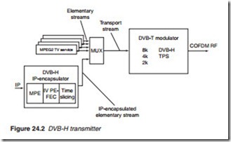
The enhanced FEC, the MPE and the time-slicing technique are directly aligned with each other (Figure 24.2). The IP input streams provided by different sources as individual elementary streams are multiplexed according to the time-slicing method. The MPE-FEC error protection is calculated separately for each individual elementary stream. This is fol- lowed by encapsulating the IP packets and embedding them into the transport stream. As can be seen, all relevant data processing is carried out before the transport stream interface in order to guarantee compatibility to a DVB-T transmission network.
Enhanced signalling
At the physical layer, DVB-H introduces three extensions to satisfy the demands of handheld sets, namely an enhanced signalling, a new 4K mode option and in-depth interleaving.
As was described in Chapter 8, in DVB-T one of the COFDM channel is reserved for transmitter parameter signalling (TPS) to carry information such as the mode (2K or 8K), guard interval length, modulation type and code rate within the transmitted frame. The TPS information is carried by specified carriers spread over the entire COFDM frame. One carrier in each symbol is allocated to carry one bit of TPS using simple BPSK (Binary PSK). With DVB-H, additional information related to time slicing and whether MPE-FEC protection is used is included as an extension to the TPS channel. The purpose of the DVB-H signalling is to provide a robust and easy-to-access signalling to the DVB-H receivers, thus enhancing and speeding up service discovery. TPS also provides a faster way to access signalling than demodulating and decoding the Service Information (SI) or the MPE-section header.
As was stated in Chapter 8, DVB-T provides two OFDM modes; 2K and 8K (2048 and 8192 carriers respectively). DVB-H specifications provides for an additional mode, a 4K with 4096 carriers (Table 24.1).
The 4K mode is a compromise solution between the two other modes designed to double the SFN coverage area compared with the 2K mode. The SFN coverage area or size, known as a cell, is determined by the num- ber of carriers of the OFDM mode used. By doubling the number of carri- ers, say from 2K to 4K, the cell size also doubles, but in doing so, it also makes the network more susceptible to the effects of the Doppler frequency shifts. Conversely, a decrease in the number of carriers from say 8K to 4K, improves its effectiveness to deal with the Doppler effect. In short, the 4K mode allows for a doubling of the transmitter distance in single-frequency networks (SFNs) compared to the 2K mode and, when compared to the 8K mode, it is less susceptible to the effects of Doppler shifts. It offers a new degree of network planning flexibility: 8K mode for small, medium and large SFNs with high-speed reception, 4K mode for small and medium SFNs with very high-speed reception and 2K mode for small SFNs with extremely high-speed reception.
In-depth interleaving
The in-depth interleaving may be viewed as a spin off of the fact that DVB-H terminals would incorporate 8K symbol interleaving capability as a standard. The type of interleaving requires a large memory size in the terminal in order to process the data transmitted in one complete 8K OFDM symbol. However, if a 4K mode is used, the size of the 8K mode memory is able to process two 4K frames or alternatively four 2K OFDM symbols. The new scheme results in an increased interleaving depth for the 2K and 4K modes and in improved performance. If the full amount of the available memory is used, the resulting method is called in-depth interleaving. In-depth interleaving provides an extra level of protection against short noise impulses caused by, e.g. ignition interference and inter- ference from various electrical appliances.


