Zigzag scanning of the DCT matrix
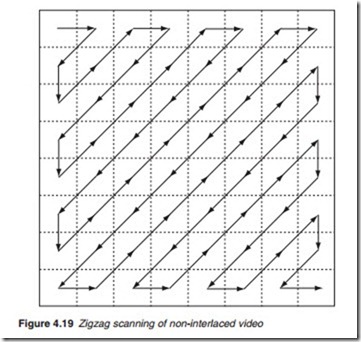
Before coding the quantised coefficients, the DCT matrix is reassembled into a serial stream by scanning the DCT cells in the zigzag pattern shown in Figure 4.19, starting at the top left-hand cell. The zigzag scan pattern makes it more likely that the coefficients having significant values are scanned first
followed by low value coefficients. For the example in Figure 4.18, the scanned order is 315, 0, -6, -3, -4, -3, -1, -2, -2, 0, 0, 0, -1, 1 and -1.
No further transmissions are necessary since the remaining coefficients are zero and thus contain no information. This is indicated by a special end of block (EOB) code, appended to the scan. Sometimes a significant coefficient may be trapped within a block of zeros, then other special codes are used to indicate a long string of zeros.
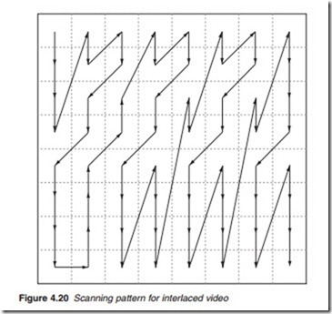
The zigzag pattern illustrated above will optimise the number of successive zero coefficients for a progressively scanned picture frame. A different pattern (Figure 4.20) has to be used when optimising the DCT for an interlaced picture scan. This is because, in a block with an interlaced field, the DCT block contains lines from one field only, and these lines must have come from a screen area of 16 lines high. In a progressive scan, the DCT block is obtained from a screen area of eight lines high. Thus, in the case of an interlaced picture, a DCT coefficient representing a vertical spa- tial frequency is taken over a vertical dimension that is twice as large as the horizontal dimension. The probability of non-zero or significant vertical frequency coefficients is therefore twice as high as the corresponding
probability for horizontal frequencies. Hence, the distribution of the inter- laced coefficients is different from the distribution of the progressive coefficients. This requires a DCT scan pattern that will favour vertical frequency coefficients twice as much as horizontal frequency coefficients and hence the pattern in Figure 4.20.

