Bidirectional prediction
The bit rate of the output data stream is highly dependent on the accuracy of the motion vector. A P-frame that is predicted from a highly accurate motion vector will be so similar to the actual frame that the residual error will be very small, resulting in fewer data bits and therefore a low bit rate. By contrast, a highly speculative motion vector will produce a highly inaccurate prediction frame, hence a large residual error and a high bit rate. Bidirectional prediction attempts to improve the accuracy of the motion vector. This technique relies on the future position of a moving matching block as well as its previous position.
Bidirectional prediction employs two motion estimators to measure the forward and backward motion vectors, using a past frame and a future frame as the respective anchors. The current frame is simultaneously fed into two motion vector estimators. To produce a forward motion vector, the forward motion estimator takes the current frame and compares it macroblock by macroblock with the past frame that has been saved in the past-frame memory store. To produce a backward motion vector, the back- ward motion estimator takes the current frame and compares it mac- roblock by macroblock with a future frame that has been saved in the future frame memory store. A third motion vector, an interpolated motion vector, also known as a bidirectional motion vector, may be obtained using the average of the forward and backward motion vectors. Each vector is used to produce three possible predicted frames: P-frame, B-frame and average or bidirectional frame (Bi-frame). These three predicted frames are compared with the current frame to produce three residual errors. The one with the smallest error, i.e. the lowest bit rate, is used.
Spatial compression
The heart of spatial redundancy removal is the DCT processor. The DCT processor receives video slices in the form of a stream of 8 X 8 blocks. The blocks may be part of a luminance frame (Y) or a chrominance frame (CR or CB). Sample values representing the pixel of each block are then fed into the DCT processor (Figure 4.10), which translates them into an 8 X 8 matrix of DCT coefficients representing the spatial frequency content of the block. The coefficients are then scanned and quantised before transmission.
The discrete cosine transform
The DCT is a kind of Fourier transform. A transform is a process which takes information in the time domain and expresses it in the frequency domain. Fourier analysis holds that any time domain waveform can be rep- resented by a series of harmonics (i.e. frequency multiples) of the original fundamental frequency. For instance, the Fourier transform of a 10-kHz square wave is the series of sine waves with frequencies 10, 30 and 50 kHz, and so on (Figure 4.11). An inverse Fourier transform is the process of
adding these frequency components to convert the information back to the time domain.
In common usage, frequency, measured in hertz, refers to temporal (i.e. time-related) frequency, such as the frequency of audio or video signals. However, frequency need not be restricted to changes over time. Spatial frequency is defined as changes in brightness over the space of a picture frame and can be measured in cycles per frame. In the picture frame (Figure 4.12), the changes in brightness along the horizontal direction can be analysed into two separate spatial frequency components:
● Zero or d.c.: grey throughout the frame representing the average bright- ness of the frame.
1 Hz: brightness changing horizontally from bright to dark then back to bright, a horizontal spatial frequency of 1 cycle per frame, equivalent to 1 Hz.
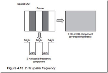
If the picture content is changed to that shown in Figure 4.13, a 2-Hz frequency component is produced together with a d.c. component. More complex video elements would produce more frequency components as illustrated in Figure 4.14. A similar analysis may be made in the vertical direction resulting in vertical spatial frequencies.
Normal pictures are two-dimensional, and following transformation, they will contain diagonal as well as horizontal and vertical spatial fre- quencies. MPEG-2 specifies DCT as the method of transforming spatial picture information into spatial frequency components. Each spatial frequency is given a value, known as the DCT coefficient. For an 8 X 8 block of pixel samples, an 8 X 8 block of DCT coefficients is produced (Figure 4.15). Before DCT, the figure in each cell of the 8 X 8 block represents the value of the relevant sample, i.e. the brightness of the pixel represented by the sample. The DCT processor examines the spatial frequency components of the block as a whole and produces an equal number of DCT coefficients to define the contents of the block in terms of spatial frequencies.
The top left-hand cell of the DCT block represents the zero spatial frequency, equivalent to 0 Hz or d.c. component. The coefficient in this cell thus represents the average brightness of the block. The coefficients in the other cells represent an increasing spatial frequency component of the block, horizontally, vertically and diagonally. The values of these coefficients are determined by the amount of picture detail within the block. The spatial frequency represented by each cell is illustrated in Figure 4.16.
coefficient values. The reduction in the number of bits follows from the fact that, for a typical block of a natural image, the distribution of the DCT coeffi- cients is not uniform. An average DCT matrix has most of its coefficients, and therefore energy, concentrated at and around the top left-hand corner; the bottom right-hand quadrant has very few coefficients of any substan- tial value. Bit rate reduction may thus be achieved by not transmitting the zero and near-zero coefficients. Further bit reduction may be intro- duced by weighted quantising and special coding techniques of the remain- ing coefficients.


