The complete VCR
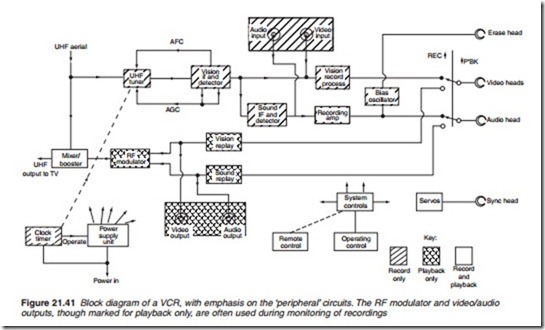
Figure 21.41 shows a block diagram of a VCR. To avoid regular plugging and unplugging operations, the VCR is permanently connected ‘in series’ with the aerial lead to the TV receiver. When the machine is off or recording a programme other than the one being viewed, it is important that normal TV reception is not affected by the machine’s presence, so a loop-through facility is provided in the aerial booster, a small RF amplifier which is per- manently powered. Its modest gain cancels the losses incurred in the extra RF plugs, sockets and internal splitting of the RF signal within the VCR.
UHF tuner and IF amplifier
Most recordings made on a home VCR come via broadcast transmissions, so the machine needs a tuner and receiver built-in to select and demodu- late broadcast programmes. An effective AGC circuit is provided to ensure
a constant signal level to the recording section, and AFC (automatic fre- quency control, sometimes known as AFT, auto fine tuning) feedback maintains correct RF tuning. Some VCRs have auto-set routines, in which they tune themselves, working from a program in the control section, and set their own clock from teletext.
