Head-tape flux transfer
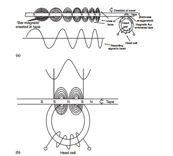
The recording head consists of a ferrite ‘ring’, with its continuity broken by a tiny gap. A coil is wound around the ring, and when energised it creates a magnetic field in the ring; this is developed across the head gap. As the tape passes the gap, the magnetic field embraces the oxide layer on the tape and aligns the ‘internal magnets’ in the tape according to the electri- cal signal passing through the head. Provided that some sort of bias is
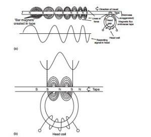
Figure 21.6 Storing flux on the tape: at (a) the flux appearing across the head gap is penetrating the oxide surface to leave magnetic patterns stored on the tape; (b) shows the effect when one complete cycle of the recorded waveform occupies the head gap—no signal transfer will take place. This point represents fex, extinction frequency present (Figure 21.5) the relationship between writing current and flux imparted to the tape is linear, so that a magnetic facsimile of the electrical signal in the head is stored in the tape, as shown in Figure 21.6a. The tape passes the head at a fixed speed, so that low frequencies will give rise to long ‘magnets’ in the tape, and high frequencies short ones.
The linear relationship between head field strength and stored flux in the tape, described above, holds true when the wavelength to be recorded on tape is long compared with the width of the head gap. However, when the wavelength of the signal on the tape becomes comparable with the head-gap width, the flux imparted to the tape diminishes, reaching zero when the recorded wavelength is equal to the width of the head gap. This is illustrated in Figure 21.6b, where it can be seen that during the passage of a single point on the tape across the head gap, the applied flux has passed through one complete cycle, resulting in cancellation of the stored flux in the tape.
This point is known as the extinction frequency (fex) and sets an upper limit to the usable frequency spectrum.
For video recording, we need a large bandwidth and a high fex. This can be achieved by reducing the head-gap width or alternatively increasing head-to-tape or writing speed. There is a practical limit to how small a gap can be engineered into a tape head. The desirability for a narrow gap means that most practical heads are made by forming a narrow V-shaped groove in the back face of the core and grinding away the front face until the V-groove is just breached. In this way, gaps of the order of microme- tres are achievable. With a typical gap of 0.3 Jlm used in domestic applica- tions, a writing speed of about 5 m/s is required. Other HF losses also occur during recording. The head is by definition inductive, so losses will increase with frequency. Eddy currents in the head will add to these losses, as will any shortcomings in the tape-to-head contact. High frequencies give rise to very short ‘magnets’ in the tape itself, and it is the nature of these to tend to demagnetise themselves. For all these reasons, the flux imparted to the tape tends to fall off at higher frequencies, as in the solid line of the graph shown in Figure 21.7. To counteract this, recording equal- isation is applied by boosting the HF part of the signal spectrum in the recording amplifier, as per the dotted line.
This is called recording equalisation, and its aim is to make the frequency/ amplitude characteristic of the signal stored on the tape as flat as possible.

