Panel drive
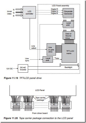
In a TFT-LCD panel, each pixel cell may be addressed by selecting two electrodes: the line (or gate) electrode and the data (or source) electrode with respective line and data drives as illustrated in Figure 11.19. 24-bit video is fed into the LCD controller which addresses each line in turn by a line select voltage which turns all the TFTs on that line on. At the same time, the controller feeds the corresponding RGB video data for the pixel cells of the selected line to the greyscale generator. The greyscale genera- tor consists of a DAC and a sample-and-hold circuit. It converts the digital greyscale value of each cell into an equivalent analogue voltage that when fed into the LC electrode produces the correct luminance. The sample-and-hold ensures the analogue value remains steady long enough for the cell to respond to any change in value. Before going into the cell electrode, the voltage is inverted by a line sync for line inversion (shown) or by a dot frequency pulse for dot inversion. Similarly, the common electrode voltage VCOM is inverted by a line sync pulse of a dot- frequency pulse. The backlight which forms a part of the panel assem- bly is fed by a sine wave in the region of 2000 V from an external d.c.–a.c. converter.
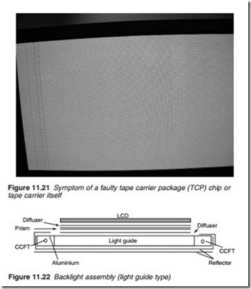
The analogue cell values are fed into the panel using a tape carrier package (TCP) in which an LSI chip is installed on a thermostabile film and sealed with plastic as illustrated in Figure 11.20. The chip may be a driver or a shift register or both delivering not an inconsiderable power to the cells, power that must be dissipated using a heat sink. The heat sink normally forms part of the panel frame. A faulty TCP IC would result in
vertical lines along the section of the screen which is fed by the particular TCP as shown in Figure 11.21. This is an un-repairable fault and the whole panel must be changed. The same symptom would be observed if the tape carrier is damaged in any way.

