Principle of operation of resonant converters
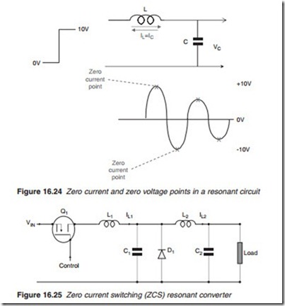
When a resonant circuit is fed with a +10 V step voltage, it oscillates resulting in what is known as ringing. The capacitor charges up to 10 V, at which point current ceases and the capacitor begins to discharge causing current to flow in the opposite direction transferring energy from the capacitor to the inductor. The current continues to flow in that direction until the capacitor is fully charged to -10 V at which point, current ceases and swings back in the opposite direction and so on as illustrated in Figure 16.24. As can be seen, the resonant waveform has zero current when the voltage is at a peak and zero voltage when it crosses the 0 V line. Resonant converters use this fact to ensure that switching takes place at one of these points.
Steady-state analysis of a basic ZCS resonant converter Refer to Figures 16.25 and 16.26. In the steady state, load current IL2 is con- stant. The cycle starts when MOSFET Q1 is turned ON by a control pulse while D1 is also ON. With capacitor C1 short circuited by D1, IL1 flows through inductor L1 and diode D1. IL1 increases in a linear fashion and
energy is stored in the inductor. When IL1 = IL2, diode current drops to zero and the diode turns OFF naturally (ZCS). With D1 open circuit, L1 and C1 form a resonant circuit. IL1 increases to a peak in a sinusoidal manner and energy is transferred to the capacitor as IC1 charges capacitor C1. Once IL1 reaches its peak (at which point the voltage across C1 is equal to the input voltage VIN), it begins to drop and when IL1 = IL2, C1 is fully charged and IC1 drops to zero. When IL1 drops further below IL2, IC1 is reversed and the capacitor begins to discharge transferring energy to inductor L2. When IL1 drops to zero, MOSFET Q1 switches OFF naturally (ZCS) keeping IL1 at zero. The capacitor continues to discharge and when its voltage falls to zero and IC1 = IL2, diode D1 switches ON naturally (ZCS) to short circuit C1 and break the resonant circuit. This state continues until Q1 is switched on by a control pulse to commence the next cycle and so on. As can be seen,
the period Q1 remains ON is fixed by the resonant frequency of L1 and C1 while the time it is OFF is determined by the control pulse which is varied as necessary to regulate the voltage. This type of resonant converter is known as ‘fixed on-time, varied off-time’. The ON period of the power MOS- FET switch is the resonant period of L1/C1, known as the tank. For heavy loads, the resonant off-time is made shorter.

