Gravity Hot-Water Heating Systems
Gravity hot-water heating systems can still be found in older buildings. They are commonly identified by their cast-iron boilers and the large-diameter wrought iron or black iron supply mains used to deliver the hot water to the rooms. These older cast-iron boilers were fired originally by coal or wood but have been converted to oil or gas use; see Chapter 16, “Boiler and Furnace Conversions” in this volume.
The difference in weight (specific gravity) of the water at different temperatures is used to circulate the water in a gravity hot- water heating system. In other words, the motive force is due to the difference in density of the water at different temperatures; heavy when cold, light when hot. For this reason, gravity systems are also referred to as thermal, or natural, hot-water heating systems.
A gravity hot-water heating system produces a continuous, uniform heat. The water temperature can be regulated by a manually operated draft damper located in each room. The room air temperature can be regulated by turning the radiator valve.
In order for the hot water to transmit heat from the boiler (heating unit) to the radiators or other heat-emitting devices, there must be a constant movement (circulation) of the water from the heater to the radiators and back again. As mentioned above, this circulation in gravity systems is due to the difference in density (weight per
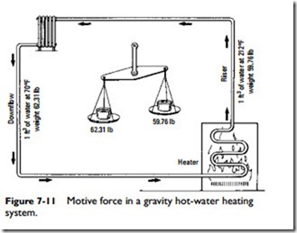
unit volume) of water at different temperatures. For example, 1 ft3 of water at, say, 68°F weighs 62.31 lb; at 212°F it will weigh 59.82 lb. This difference in weight is 2.49 lb (62.31–59.82), which is available to cause circulation, as shown in Figure 7-11.
The difference in weight is caused by the expansion of water as its temperature is increased. This principle is illustrated in Figure 7-12. Note that the top surface abcd of the cubic foot A has expanded to A‘, an increase in volume represented by the linear increase aa’.
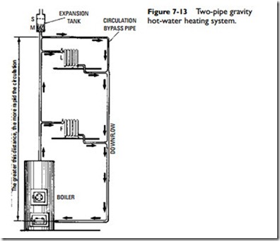
In the two-pipe system illustrated in Figure 7-13, the unbalanced weight between the water in the riser and downflow pipe forms a
motive force that causes the water to circulate through the system as indicated by the arrows.
The two-pipe gravity hot-water system illustrated in Figure 7-13 is equipped with an expansion tank. In operation, after the fire is started, the temperature of the water in the boiler rises, and the water expands. This disturbs the equilibrium of the system, causing the colder and heavier water in the downflow pipe to flow downward, pushing the warmer and lighter water in the riser upward, thus starting circulation.
A circulation, or bypass, pipe is provided to form a continuous path for the flowing water in the event that all the radiators are shut off. In the absence of this provision, all the water in the upflow pipe would be pushed up into the expansion tank followed by steam.
The expansion tank provides two essential functions for this sys- tem. As the water is heated, it expands and the tank provides space for this increase in volume. Thus, as it is heated, the water will expand from, say, elevation M to elevation S in the expansion tank
(Figure 7-13). The higher the elevation of the tank, the greater the pressure that may be brought on the water in the boiler (due to the head). As a result, the system may be worked at higher temperatures when desired.
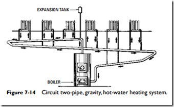
Sometimes a special piping circuit can be built into a heating system (see Two-Pipe, Direct-Return System and Two-Pipe, Reverse- Return System in this chapter). In the two-pipe gravity hot-water heating system illustrated in Figure 7-14, a single main is taken from the boiler to a high point under the basement ceiling and then is pitched along its run as much as possible to the return inlet of the boiler. The piping circuit formed by this main consists of a closed loop of extra-large pipe in the basement having a pitch of not less than 1⁄2 in per 10 ft of run. The main supplies all the risers to the radiators above. This arrangement is not as efficient as the two-pipe system illustrated in Figure 7-13, and for this reason the circuit main should be of very liberal size to reduce friction to a minimum.
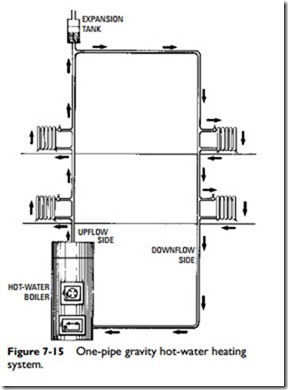
In the so-called one-pipe system shown in Figure 7-15, special distribution tees are employed to deflect part of the water from the main into the radiators while letting the balance flow through the main to the next radiator. This is called a one-pipe system because one pipe serves both inlet and outlet of each radiator. In this system, there must be an upflow side L and a downflow side F. Thus, there are in reality two main pipes, but in function only one main pipe. The downflow may be considered as a continuation of the upflow instead of as a second pipe. The major objection to this system (as well as to the one illustrated in Figure 7-14) is a lack of uniformity
in heat distribution, primarily because the radiators on the upflow side L are hotter than those on the downflow side F.
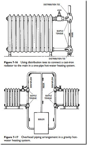
Distribution tees (Figure 7-16) are used in this one-pipe system. They are provided with a baffle tongue, which deflects part of the water from the main in and out of the radiator while bypassing the balance along the line as indicated by the arrows in the illustration.
Another piping system used to distribute the hot water is the overhead arrangement illustrated in Figure 7-17. This is practically the same as the so-called one-pipe system (Figure 7-15), except that it has a divided circuit at the high point connecting with the downflow mains. No air vents are necessary because the arrange- ment is such that all air works to the top and passes off into the expansion tank. One advantage of this system is a better and
more uniform distribution of the heat. The hot water enters each downflow pipe at the same temperature, equalizing the heat given off by each pair of radiators.
Although the overhead piping arrangement is not suited to all classes of buildings, there are many buildings, such as apartments, stores, office buildings, and hotels, where the general arrangement lends itself to this system.
