FIELD WIRING
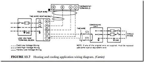
The installation of a new furnace requires you to follow a factory diagram furnished in a booklet that ac- companies the unit. The wiring to be done in the field is represented by the dotted lines in Figure 13.7. All electrical connections should be made in accordance with the National Electrical Code and any local codes or ordinances that might apply.
WARNING: The unit cabinet must have an uninterrupted or unbroken electrical ground to minimize
personal injury if an electrical fault should occur. This may consist of electrical wire or approved conduit when installed in accordance with existing electrical codes.
Low-Voltage Wiring
Make the field low-voltage connections at the low-voltage terminal strip shown in Figure 13.7. Set the ther- mostat heat anticipator at 0.60 ampere (or whatever is called for by the manufacturer). If additional controls are connected in the thermostat circuit, their amperage draw must be added to this setting. Failure to make the setting will result in improper operation of the thermostat.
With the addition of an automatic vent damper, the anticipator setting would then be 0.12 ampere. The anticipator resistor is in series with whatever is in the circuit and is to be controlled by the thermo- stat. The more devices that are controlled by the thermostat, the more current will be drawn from the transformer to energize them. As the current demand increases, the current through the anticipator is also increased. As you remember from previous studies, a series circuit has the same current through each component in the circuit.
Thermostat Location
The room thermostat should be located where it will be in the natural circulating path of room air. Avoid locations where the thermostat is exposed to cold-air infiltration, drafts from windows, doors or other openings leading to the outside, air currents from warm- or cold-air registers, or to exposure where the natural circulation of the air is cut off, such as behind doors and above or below mantels or shelves. Also keep the thermostat out of direct sunlight.
The thermostat should not be exposed to heat from nearby fireplaces, radios, televisions, lamps, or rays from the sun. Nor should the thermostat be mounted on a wall containing pipes or warm-air ducts or a flue or vent that could affect its operation and prevent it from properly controlling the room temperature. Any hole in the plaster or panel through which the wires pass from the thermostat should be adequately sealed with suitable material to prevent drafts from affecting the thermostat.
Printed Circuit-Board Control Center
Newer hot-air furnaces feature a printed circuit control. The board shown in Figure 13.8 is such that it is easy for the technician installing the furnace to hook it up properly the first time. The markings are de- signed to make it easy to connect the furnace for accessories if needed. Figures 13.9 and Figure 13.10 show the factory-furnished schematic. See if you can trace the schematic and locate the various points on the printed circuit boards.

