INDUCED DRAFT FANS
Sometimes a chimney is too small to provide enough updraft to convey the products of combustion from the boiler to the outside atmosphere. When it is evident that natural venting will be inadequate, a mechanical draft inducer can be used to increase the capacity of the chimney. These devices are used with both gas- and oil-fired boilers.
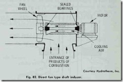
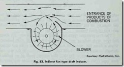
The two principal types of induced draft fans are: ( 1) direct fan type draft inducer and (2) induced flow type draft inducer. When a direct fan type draft inducer is used, the gases are drawn through an inlet located on the side, top or bottom of the unit and discharged as shown in Fig. 82. The moving par,ts of an induced flow type draft inducer (Fig. 83) are located outside the path of the hot flue gases. Cool outside air is introduced through the blower section of the unit. This creates suction at the throat of the inducer body which in turn increases the flow rate of the flue gases.
The draft created by the induced draft fan should closely match the demand. If the size of the draft inducer is correctly estimated, any dilution and excessive cooling of the flue gases (a condition that may result in condensation) will be greatly reduced.
Many boiler manufacturers will recommend the size draft inducer to be used with specific boiler models, and will provide data for making the appropriate calculations. Manufacturers of draft in ducers are similarly helpful.
CONTROL OF EXCESSIVE DRAFT ON GAS-FIRED BOILERS
Sometimes a boiler installation will have excessive draft con ditions as a result of oversized chimneys or other factors. Draft conditions in excess of the draft design limits of the boiler will re duce the combustion efficiency of the boiler, resulting in higher fuel costs and possible pilot problems.
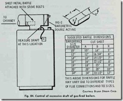
A suggested method of controlling the draft on such installa tions is to install a sheet metal baffle, or restrictor, in the flue con nection at the boiler (Fig. 84). This baffle may be inserted in a tee as shown and secured with stove bolts after the proper draft is obtained by measurements with a draft gauge. If the barometric control is installed in the side of the breeching by means of a draft control collar, the same method of baffling may be used with the baffle restricting the breeching between the boiler and the barometric control. In this method of baffling, the breeching be tween the barometric control and breeching should not be restricted.
The baffle installation is correct if the gate of the barometric control is approximately half open while the gas burner is oper ating, and the draft measurement is at or below the operating design of the boiler. The draft limit for a boiler can be obtained from the manufacturer’s specifications. For example, Bryan at mospheric gas boiler burner units are designed to operate at very low draft, never to exceed .01”’ W.C.
Always check with ·the local gas company regarding the use of baffles. Caution should be exercised to insure against over restric ting the flue. Always be certain that there is a very slight draft after the baffle is secured in position.
TANKLESS WATER HEATERS
Some boilers are manufactured with the option of using a tankless water heater. This device consists of an immersion coil inserted in a steam or hot-water space heating boiler to provide domestic and commercial service hot water. It is called a “tank less” water heater, because no storage tank is used to store the heated water during periods of low demand.
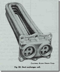
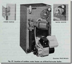
The immersion coil is made of small diameter copper tubes which are either straight with U-bends at the end (Fig. 85) or formed in the shape of a spiral (Fig. 86). Typical locations on steam and hot-water space heating boilers are illustrated in Fig.87 As shown, the tankless heater is installed in the nipple port on cast-iron hot water boilers. On steam boilers, it is installed in the left hand side of a special back section at a point well below the waterline. A uniform water temperature is maintained by a thermostatic three-way mixing valve installed in the supply line leading from the immersion coil.
Because these immersion coils function as a heat exchanger type device and operate on an indirect heating principle, they are also variously referred ,to as an indirect water heater, indirect heat exchanger, or heat exchanger coil.
In other applications, immersion coils provide hot water radi ation from a steam boiler, hot water for snow melting, heated water for pools, and industrial process water.
Additional information about water heaters, including suggestions for estimating the hot water allowance, can be found in Chapter 4, Volume 3 (WATER HEATERS).
LEAKING COILS
On occasions, the coil of a tankless or indirect water heater installed in a boiler will leak , allowing high pressure water into the boiler water and resulting in a rise in the boiler presure. This, in turn , can cause the relief valve to open and fail to close again tightly , or it can cause the boiler pressure to rise above the set ting of the pressure reducing valve. These symptoms are often wrongly attributed to a valve malfunction when the actual cause may be a leaking coil.
You can determine whether or not the problem is a leaking coil by taking the following steps:
1. Shut off the feed valve and or break the connection to the coil.
2. Check the pressure reading in the boiler.
3. Wait about 8 hours and check the boiler pressure reading again.
If the pressure reading has remained approximately the same over the 8 hour period, it is a strong indication that the coil is leaking. On ,the other hand, if the boiler pressure continues to rise, the problem may lie elsewhere in the system.
