Equal Friction Method
The equal friction method of sizing ducts is recommended because it does not require a great deal of experience in the selection of proper velocities in the various sections of the duct system. It is necessary to select the main duct velocity consistent with good practice from a standpoint of noise for a particular building or application. In this duct-sizing method, the duct design is based primarily on a consistent pressure loss for each foot of duct.
Proportioning for equal friction is more advantageous than reducing the velocity in a haphazard manner because the friction calculation is greatly simplified. In calculating the friction, it is necessary to know only the length of the longest run, the number and size of elbows, and the diameter and velocity of the largest duct. The friction loss is exactly the same as though the entire amount of air were carried the whole distance through the largest duct.
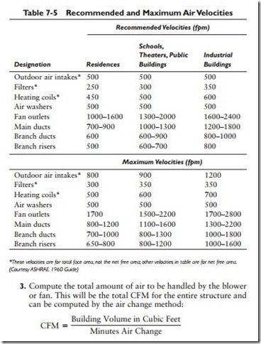
The air velocities listed in Table 7-5 have been found to accomplish satisfactory results in engineering practice. Where quiet operation is essential, the blower or fan should be selected on the basis of a low outlet velocity. This will also result in lower operating costs.
The following steps are involved in sizing ducts by the equal friction method:
1. Compute the total volume (in cubic feet) of the structure.
2. Compute the cubic-foot volume of each room in the structure to be supplied with heated or cooled air. The volume of each room should be expressed as a percentage of the total volume of the structure. For example, a room having a volume of 6000 cubic feet would represent 10 percent of a structure having a total volume of 60,000 cubic feet.
 4. Determine the portion of the total amount of air to be delivered to each room. This is computed by multiplying the total CFM for the structure by the room volume percentage (see step 2). For example, if the blower or fan handles a required 15,000 CFM, then the room described in step 2 would receive 1500 CFM (15,000 CFM x 10% = 1500 CFM).
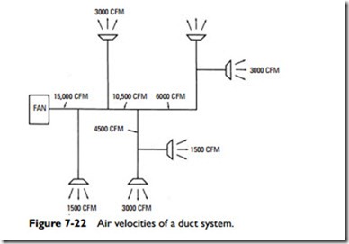
5. Determine the design and location of the duct runs (supply, branch, and return runs) (see Figure 7-22) and then locate the supply air outlets and return air openings for each room to give the most uniform distribution of air. Each outlet should be selected for suitable air velocity and throw (the manufacturer’s catalog will provide the necessary data).
6. Determine the total CFM for the main supply duct before any branch ducts are reached. This will be equal to the total CFM for the entire structure.
7. Determine the allowable air velocity in the main supply duct (see Table 7-5). For a commercial building such as the one represented by this example (that is, 60,000 cubic feet), the air velocity in the main duct will be 1300 fpm.
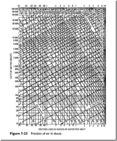
8. Determine the static pressure drop from Figure 7-23. Since the supply duct must carry 15,000 CFM, locate 15,000 on the ver- tical scale on the left side of the friction chart in Figure 7-23. This will be found a little over halfway between 10,000 and 20,000 on the scale. Draw a line horizontally across the chart to where it intersects at a point halfway between the diagonals representing 1200 and 1400 fpm (that is, 1300 fpm). This gives a static pressure drop for the main duct of approximately 0.04
inch of water per 100 feet of duct. Use the static pressure drop of 0.04 inch as a constant for the entire duct system.
9. Use Figure 7-23 to compute the round duct diameter for each branch duct. For example, branch No. 10 in Figure 7-22 will have a diameter of approximately 19 inches. This is determined by finding the 1500 CFM on the left-hand column of the chart in Figure 7-23 (halfway between 1000 and 2000 CFM) and moving horizontally in a straight line to the right until it inter- sects with the vertical line representing a static pressure drop of 0.04 inch. The two lines intersect at a point representing an approximate round duct diameter of 19 inches.
10. Using the same data in step 9, determine the air velocity for each branch duct. The air velocity of duct branch No. 10, for example, will be approximately 750 fpm.
11. Size the return air duct system by first determining the amount of return air required. In step 4, the amount of supply air for the structure was stated as being 15,000 CFM. The amount of return air (CFM) required can be determined by subtracting the amount of fresh air intake from the supply air (CFM). The amount of fresh air intake (CFM) can be determined from the following formula:
12. After the duct sizes have been determined, it is necessary to compute the external static pressure of the system so that a suitable fan can be selected which will handle the required volume of air (in this case 15,000 CFM) against the total static pressure of the system. In the equal friction method, the total external static pressure drop of the system is obtained by calculating the external static pressure for the duct run having the highest total resistance. For the duct system shown in Figure 7-22, this can be obtained by adding the total length of the main supply duct from the point where the air enters the system (that is, duct sections numbered 1–6) and the equiva- lent straight pipe length of all elbows and transitions. This total length figure is then multiplied by the 0.04 inch static pressure constant (see step 9) to obtain the total resistance (that is, the total external static pressure drop) for the duct system. If, for example, the total length of duct was found to be 406 feet, the total resistance would be 0.1624 inch (406 ft -:- 100 ft = 4.06 ft x 0.04 = 0.1624 in).
13. The total resistance for the return duct run is determined in the same manner as described for the supply air run. Because it represents less air volume than the supply air (return air = supply air – fresh air intake), it will always be a smaller figure than the static pressure determined for the supply duct run.
As a rule-of-thumb, the return-run static pressure will be about 25 percent of the supply-run static pressure.
14. The total static pressure against which the blower or fan must operate includes the following:
a. Total resistance of the supply air duct system (that is, the total external static pressure drop).
b. Total resistance of the return air duct system (that is, the total external static pressure drop).
c. Total internal static pressure losses (that is, resistance through filters, cooling coils, and other forms of equipment).
Related posts:
Incoming search terms:
- equal friction method
- Duct friction chart is prepared on
- equal friction method duct design procedure
- equal friction method example
- friction chart for duct design
- utility of duct friction chart
- equal friction method for duct design
- duct design methods
- duct friction chart
- duct sizing and pressure loss calculation pdf
- duct friction chart belong which scale
- advantages of equal friction
- method of duct
- Manual duct design and calculation equal friction method
- Duct friction chart is prepared on which scale
- friction chart of duct design
- in designing ducts the equal friction method is ideal
- duct design method
- hvac duct design example
- advantages of equal friction method
- equal friction losses method
- calculation of duct sizing by equal friction method example
- equal friction method advantages and disadvantages
- how to calculate duct size using equal friction
- value of friction in equal friction method
- in designing ducts the equal friction method is ideal?
- Duct sizing Table by equal friction method
- duct scale
- duct sizing example problem
- duct sizing method
- ducting design sample problem
- duct sizing equal friction method
- duct sizing by using equal friction method
- duct sizing METHOD EQUAL
- Duct size calculation based on equal friction method explanation
- duct pressure loss in circular duct per 100 ft
- duct system problem using friction chart
- when equal friction method of designing ducts are prefered
- define equal friction method
- define equal pressure drop method
- design of duct by equal friction method step by step
- difference bw velocity reduction method and equal friction method
- duct desien using equal friction method
- duct design problem equal friction
- duct design procedure by using equal friction method
- duct design velocity method
- duct desin mthod advantages
- duct equal friction method
- Duct friction chart is prepared
- Duct friction chart is prepared on answer


