CROSSOVER BURNER
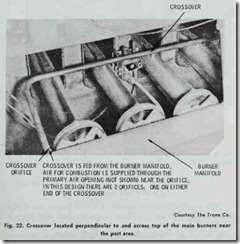
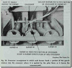
Most modern gas-fired furnaces consist of several individual heat exchanger sections with a gas burner inserted in each section. In this arrangement, all burners must fire almost simultaneously or there will be the danger of unburned gas flowing into the combus tion chamber. Simultaneous ignition can be provided by installing a crossover burner across the top of the main burners near the port area. Figs. 22 and 23 show the types of crossovers used in Trane gas-fired furnaces.
GAS PILOT ASSEMBLY
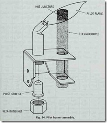
The gas pilot assembly consists of a pilot burner and a pilot safety device (Fig. 24). The most commonly used pilot safety is the thermocouple lead operating in conjunction with a companion valve or switch. The thermocouple itself is actually a miniature generator which converts heat (from the pilot flame) into a small electrical current. The upper half of the thermocouple is located in the pilot flame. As long as the pilot flame is operating, an electrical circuit is maintained between the pilot burner and the gas valve. If the pilot flame goes out, the circuit between the thermocouple and the gas valve is broken. As a result, the gas valve closes and shuts off the gas flow to the pilot burner.
Other types of pilot safety devices used with gas-fired furnaces are described in Chapter 5, Volume 2 (GAS AND OIL CON TROLS).
PILOT BURNER ADJUSTMENT
It is sometimes necessary to adjust the pilot flame. On some combination gas controls a pilot adjustment screw is provided for this purpose. On units using natural gas, the screw should be ad justed until the pilot flame completely envelopes the thermocouple. If propane gas is used, the screw should be wide open.
Sometimes a pilot gas regulator is used on a furnace to control pressures in areas where gas pressure variation are great. The pilot valve is placed in wide open position and pilot flame adjustments are made by adjusting the gas pressure regulator.
GAS INPUT ADJUSTMENT
The gas input of a furnace must not be greater than that speci fied on the rating plate. However, it is permissible to reduce the gas input to a minimum of 80 percent of the rated input in order to balance the load.
The gas input can be checked by timing the flow through the meter. The procedure for clocking the meter is as follows:
1. Turn off all gas units connected through the meter except the furnace. The main burners of the furnace must be on for the timing check.
2. Time one complete revolution of the hand (or disc) on the meter. The hand should be the one with the smallest cubic footage per revolution (usually 1h or 1 cubic foot per revo lution on small meters and 5 cubic feet on large meters).
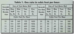
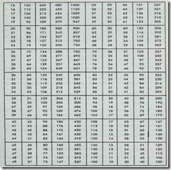
3. Using the size of the test meter dial (1h, 1, 2, or 5 cubic feet) and the number of seconds per revolution, determine the cubic feet per hour from the appropriate column in Table 1.
4. Determine the actual Btu per hour input of the burner by multiplying the cubic feet per hour rate (obtained in Step 3) by the Btu per cubic feet of gas (obtained from the local gas company).
By the way of example, let’s assume that you have contacted the local gas company and they have given you a value of 1040 Btu per cubic foot. When you clock the meter, you find that it takes exactly 18 seconds for the hand to make one complete revo lution on the 1h cubic foot meter dial. With this information, turn to Table 1 and find 18 seconds in the extreme left hand column. Opposite the value 18 seconds under the lh cubic foot column heading read 100 cubic feet. The rest is simple multiplication:
100 cu. ft. per hour X 1040 Btu per cu. ft.
= 104,000 Btu per hour.
If the Btu per hour rate is not within 5% of the desired value, change the burner orifices or adjust the pressure regulator. Pres sure regulator setting changes are only used for minor adjustments in Btu input. Major adjustments are made by changing the burner orifices.
When making adjustments, remember the following: Btu inpllt may never be less than the minimum or more than the maximum on the rating plate.
There is no meter to clock on furnaces fired with propane. The burner orifices on these units are sized to give the proper rate at 11 inches \V.C. (water column) manifold pressure.
After the correct Btu input rate has been determined, adjust the burner for the most efficient flame characteristics (see COMBUS TION AIR ADJUSTMENTS).
HIGH ALTITUDE ADJUSTMENT
For elevations abol’e 2000 feet, the Btu input should be reduced (derated) 4 % for each 1000 feet above sea level. This adjustment is required because of the increase in air volume at higher eleva tions. Air expands at approximately 4% per 1000 feet of elevation. At elevations above 2000 feet, the volume of air required to sup ply enough oxygen for complete combustion exceeds the maximum air inducing ability of the burners. Because the primary air volume cannot be increased, the gas flow (input) must be decreased (i.e. derated).
CHANGING BURNER ORIFICES
A gas-fired furnace is supplied with standard burner orifices for the gas shown on the rating plate. The orifice size will depend on the calorific value of the gas (Btu per cubic foot) and the mani fold pressure (3.5 inches W.C. for natural gas and 11 inches W.C. for LP gas). The burner orifice size partially determines the firing rate by allowing only a predetermined volume of gas to pass. An orifice that is too large will allow too much gas to pass through into the burner. This condition sometimes results in overheating the heat exchanger, or restricting the air inducing ability of the burner.
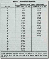
The gas burner orifices supplied with a furnace are suitable for average calorific values of gas at the listed manifold pressures. Ta ble 2 lists the various orifice capacities for different drill sizes. The procedure for determining the suitability of a particular drill size is as follows:
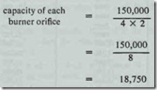
1. Divide the total Btu input of the furnace by the total num ber of burner orifices in the unit.
2. From Table 2, select the burner orifice size closest to the calculated value (plus or minus 5%) for the gas used.
This procedure can be illustrated by determining the most suit able drill size for a 150,000 Btu input gas-fired furnace. This fur nace has 4 burners with 2 orifices per burner, and uses natural gas.
In Table 2, the figure closest to 18750 in the left hand column (Natural Gas) is 19,000. The drill size opposite this figure is #46.
