DEVELOPING A PROGRAM
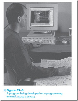
This circuit will now be developed into a program that can be loaded into the programmable controller. Figure 59–3 shows a program being developed on a computer. Assume that the controller has an I/O capacity of 32, that I/O terminals 1 through 16 are used as inputs, and that terminals 17 through 32 are used as outputs.
Before a program can be developed for input into a programmable logic controller, it is necessary to assign which devices connect to the input and output terminals. This circuit contains four input devices and four output devices. It is also assumed that the motor starter for this circuit contains an overload relay that contains two contacts instead of one. One contact is normally closed and will be connected in series with the coil of the motor starter. The other contact is normally open and is used to supply an input to a programmable logic controller. If the motor should become overloaded, the normally closed contacts will open and disconnect the motor from the line. The normally open contacts will close and provide a signal to the programmable logic controller that the motor has tripped on over- load. The input devices are as follows:
1. Normally closed stop pushbutton.
2. Normally open start pushbutton.
3. Normally open overload contact.
4. A float switch that contains both a normally open and normally closed contact.
The four output devices are:
1. Solenoid valve A.
2. Solenoid valve B.
3. Motor starter coil M.
4. Solenoid valve C.
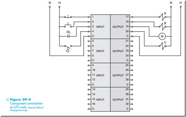
The connection of devices to the inputs and outputs is shown in Figure 59–4. The normally closed stop button is connected to input 1, the normally open start button is connected to input 2, the normally open overload contact is connected to input 3, and the float switch is connected to input 4.
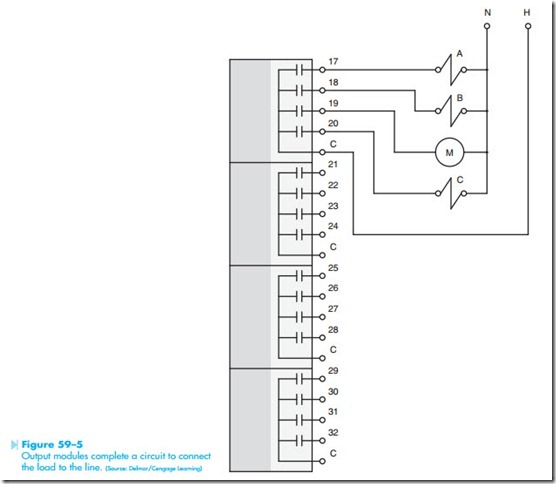
The outputs for this PLC are 17 through 32. Out- put 17 is connected to solenoid A, output 18 is connected to solenoid B, output 19 is connected to the coil of the motor starter, and output 20 is connected to solenoid C. Note that the outputs do not supply the power to operate the output devices. The outputs simply complete a circuit. One side of each output device is connected to the grounded or neutral side of a 120-VAC power line. The ungrounded or hot conductor is connected to the common terminal of
the four outputs. A good way to understand this is to imagine a set of contacts controlled by each output as shown in Figure 59–5. When programming the PLC, if a coil is given the same number as one of the outputs it will cause that contact to close and connect the load to the line.
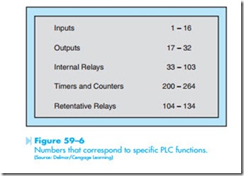
Unfortunately, programmable logic controllers are not all programmed the same way. Almost every manufacturer employs a different set of coil numbers to perform different functions. It is necessary to consult the manual before programming a PLC with which you are not familiar. In order to program the PLC in this example, refer to the information in Figure 59–6. This chart indicates that numbers 1 through 16 are inputs. Any contact assigned a number between 1 and 16 will be examined each time the programmable logic controller scans the program. If an input has a low (0 volt) state, the con- tact assigned that number will remain in the state it was programmed. If the input has a high (120-volt) state the program will interpret that contact as having changed position. If it was programmed as open the PLC will now consider it as closed.
Outputs are 17 through 32. Outputs are treated as coils by the PLC. If a coil is given the same number as an output, that output will turn on (close
the contact) when the coil is energized. Coils that control outputs can be assigned internal contacts as well. Internal contacts are contacts that exist in the logic of the program only. They do not physically exist. Because they do not physically exist, a coil can be assigned as many internal contacts as desired and they can be normally open or normally closed.
The chart in Figure 59–6 also indicates that internal relays number from 33 to 103. Internal relays are like internal contacts. They do not physi- cally exist. They exist as part of the program only. They are programmed into the circuit logic by inserting a coil symbol in the program and assign- ing it a number between 33 and 103.
Timers and counters are assigned coil numbers 200 through 264, and retentive relays are num- bered 104 through 134.


