MANIFOLD PRESSURE ADJUSTMENT
A suitable manifold pressure is important to efficient furnace operation. If the gas pressure is too low, it will cause rough igni tion, incomplete and inefficient combustion, and incorrect fan con trol response. An excessively high manifold pressure may cause the burners to overfire the heat exchanger. Overfiring the heat ex changer not only reduces the life of this component, it also may result in repeated cycling of the burner on the high limit control.
Manifold pressure should be set at 3.5 inches W.C. for natural gas. Control manufacturers normally preset the pressure regulator in natural gas valves at the time of manufacture so that natural gasunits are fired at this 3.5 inches W.C. rate. Only sma11 variations in the gas flow should be made by adjusting the pressure regulator. This adjustment should never exceed plus or minus 0.3 inches
W.C. Major changes in the gas flow should be made by changing the size of the burner orifice (see below).
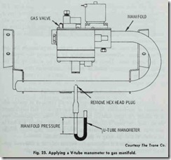
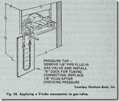
The manifold gas pressure can be tested by using a U-tube water manometer (Fig. 25). The manometer is connected to the manifold through an opening covered by a Ys inch plug cap. The pressure test must be run while the unit is operating. On Dunham Bush gas-fired furnaces, the test is run through an opening in the gas valve (Fig. 26). The furnace manufacturer’s insta11ation litera ture should contain instructions for testing the manifold pressure.
Once you have determined the manifold pressure, you may find it necessary to adjust it for better operating characteristics. Manifold pressure can be increased by turning the adjusting screw clockwise, and decreased by turning it counterclockwise.
LP gas units are fired at 11 inches W .C. manifold pressure. LP gas (propane and butane) is heavier than natural gas and has a higher heating value. As a result, LP gas needs more primary air for combustion. Thus, a higher manifold pressure is required to induce the greater volume of primary air into the burner than is the case in natural gas units.
An LP furnace does not have a pressure regulator in the gas valve. Pressure adjustments are made by means of the regulator at the supply tank. These adjustments must be made by the in staller, and regularly checked by the serviceman for possible malfunctions.
COMBUSTION AIR ADJUSTMENT
Primary air shutters are provided on all furnaces to enable ad justment of the primary air supply. The purpose of this adjustment is to obtain the most suitable flame characteristics. Experience has shown that the most efficient burner flame for natural gas has a soft blue cone without a yellow tip. For propane gas, there should be a little yel1ow showing in the tips of the flame.
The procedure for adjusting the primary air on a Coleman gasfired furnace may be summarized as follows:
1. Light the pilot burner.
2. Tum up the setting on the room thermostat until the main burners come on.
3. Allow the main burners 10 minutes to warm up.
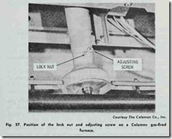
4. Loosen lock nut on adjusting screw (Fig. 27).
5. Turn adjusting screw IN (clockwise) until yellow tip ap pears in the flame.
6. Tum adjusting screw OUT (counterclockwise) until the yellow tip just disappears.
7. Hold adjusting screw and tighten lock nut.
8. Repeat Steps 4-7 on each of the other burners.
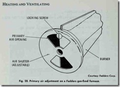
On a Fedders gas-fired furnace, a locking screw is located above the primary air opening on each gas burner (Fig. 28). The pri mary air adjustment procedure is as follows:
1. Loosen the locking screw at the base of the burner.
2. Adjust the air shutter opening to a position that gives a slight yellow tip on the end of the flame.
3. Open the air shutter until the yellow tip just disappears.
4. Tighten the locking screw.
5. Repeat Steps 1-4 for each of the burners.
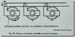
A primary air shutter assembly is provided on all Carrier gas fired furnaces in order to simplify the adjustment procedure. As shown in Fig. 29, adjustment of the end burner results in the simul taneous adjustment of all burners.
After the primary air adjustments have been made, check to see that the burners are level. The burner flames should be uniform and centered in the heat exchanger (see HEAT EXCHANGER in this chapter).
Before allowing the furnace to continue operating, you must check to see that it has the proper draft. This can be done by pass ing a match along the draft hood opening. If the vent is drawing properly, the match flame will be drawn inward (i.e. into the draft hood). If the furnace is not receiving proper draft, the products of combustion escaping the draft hood will extinguish the flame. The draft must be corrected before operating the furnace.
GAS SUPPLY PIPING
The gas supply piping (also referred to as the gas service piping) must be sized and installed in accordance with the recommenda tions contained in the latest edition of “American National Stand ards for Installation of Gas Appliances and Gas Piping” (ANSI Z21.30-1964) and “Piping for Gas Appliances” (NFPA No. 54- 1964). The location of the main shutoff valve will usually be speci fied by local codes or regulations. Consult the local codes or regu lations for recommended sizes of pipe for the required gas volumes. Local codes or regulations always take precedence over national standards when there is a conflict between the two.
Generally I inch supply pipe is adequate for furnace inputs up to 125,000 Btu/hr. A 1;4 inch pipe is recommended for higher inputs. The inlet gas supply pipe size should never be smaller than lh inch. The gas line from the supply should serve only a single unit.
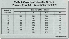
Table 3. Capacity of pipe (Cu. Ft./Hr.) (Pressure Drop 0.3- Specific Gravity 0.60)
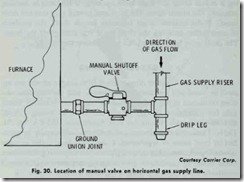
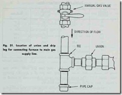
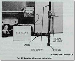
A drip leg (also called a dirt leg or a dirt trap) should be in stalled at the bottom of the gas supply riser to collect moisture or impurities carried by the gas. A manual main shutoff valve should be installed either on the gas supply riser or on the horizontal pipe between the riser and ground union joint Figs. 30 and 31). The lo cation of the main shutoff valve will usually be specified by local codes and regulations.
The ground union joint should be installed between the manual main shutoff valve and the gas control valve on the furnace or boiler (Fig. 32). The ground union joint provides easy access to the gas controls on the unit for servicing or repair.
SIZING GAS PIPING
The gas supply pipe should be sized per volume of gas used and allowable pressure drop. The pipe must also be of adequate size to prevent undue pressure drop. The diameter of the supply pipe must at least equal that of the manual shut off valve in the supply riser. Minimum acceptable pipe sizes are listed in Table 3.
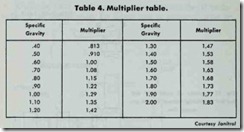
The volume rate of gas in cubic feet per hour is determined by dividing the Btu per hour required by the furnace by the Btu percubic foot of gas being used. The cubic feet per hour value can then be used to determine pipe size for gas of a specific gravity other than 0.60. The data used for these calculations is listed in Tables 3 and 4. The procedure is as follows:
1. Multiply the cubic feet per hour required by the multiplier (Table 4).
2. Find recommended pipe size for length of run in Table 3. Tables 3 and 4 apply to the average piping installation where four or five fittings are used in the gas piping to the furnace. Exist
ing pipe should be converted to the proper size of pipe where
necessary. In no case should pipe less than % inch diameter be used. Any extensions to existing piping should conform to Tables 3 and 4.
