The slip factor
Introduction
Even under ideal (i.e., frictionless) conditions, the relative flow leaving the impeller of a compressor or pump will receive less than perfect guidance from the vanes and the real flow is said to slip. If the impeller could be imagined as being made with an infinite number of infinitesimally thin vanes, then an ideal flow would be perfectly guided by the vanes and would leave the impeller at the vane angle. Figure 7.12 compares the relative flow angle, β2, obtained with a finite number of vanes, with the vane angle, β0 .
A slip factor may be defined as2
![]() where cθ2 is the tangential component of the absolute velocity and related to the relative flow angle β2. The hypothetical tangential velocity component is related to the vane angle β0 . The slip velocity is given by cθs 5 cθ20 2 cθ2 so that the slip factor can be written as
where cθ2 is the tangential component of the absolute velocity and related to the relative flow angle β2. The hypothetical tangential velocity component is related to the vane angle β0 . The slip velocity is given by cθs 5 cθ20 2 cθ2 so that the slip factor can be written as
The slip factor is a vital piece of information needed by pump and compressor designers (also by designers of radial turbines as it turns out!) as its accurate estimation allows the pressure rise, the work input, and the velocity triangles at the impeller exit to be determined. There have been many attempts to determine correlations for the slip factor starting, apparently, with that of Busemann (1928) and followed by Stanitz (1952), Wiesner (1967), and many other researchers.
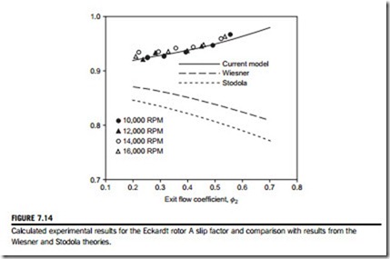
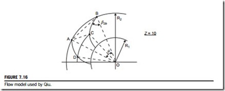
Wiesner (1967) has given an extensive review of the various expressions used for determining slip factors. Most of the expressions derived relate to radially vaned impellers ðβ0 5 0Þ or to mixed flow designs, but some are given for backward swept vane (bsv) designs. Most of the correlations presented work well for one type of impeller at the design point but fail for other designs. A recent paper presented by Qiu et al. (2011) has presented what is now called a unified slip factor model that can be applied to axial, mixed flow, and radial flow impellers and capable of being applied at both the design condition and the off-design conditions.
The relative eddy concept
Suppose that an irrotational and frictionless fluid flow is possible that passes through an impeller. If the absolute flow enters the impeller without spin, then at outlet the spin of the absolute flow must still be zero. The impeller itself has an angular velocity Ω so that, relative to the impeller, the fluid has an angular velocity of -Ω; this is termed as the relative eddy (Figure 7.13(a)). A simple explanation for the slip effect in an impeller is obtained from the idea of a relative eddy.
At outlet from the impeller, the relative flow can be regarded as a through-flow on which is superimposed a relative eddy. The net effect of these two motions is that the average relative flow emerging from the impeller passages is at an angle to the vanes and in a direction opposite to the blade motion, as indicated in Figure 7.13(b). This is the basis of the various early theories of slip.
Slip factor correlations
One of the earliest and simplest expressions for the slip factor was obtained by Stodola (1945). Referring to Figure 7.13(c), the slip velocity, cθs 5 cθ2 2 cθ2, is considered to be the product of the relative eddy and the radius d/2 of a circle, which can be inscribed within the channel.
This criterion is often applied to other than logarithmic spiral vanes, then β0 is used instead of β0. Radius ratios of typical centrifugal pump impeller vanes normally exceed the preceding limit.
For instance, blade outlet angles of impellers are usually in the range 50o # β0 # 70o with between 5 and 12 vanes. Taking representative values of β0 5 60o and Z 5 8 the right-hand side of Eq. (7.22) is equal to 1.48, which is not particularly large for a pump.
So long as these criteria are obeyed, the value of B is constant and practically equal to unity for all conditions. Similarly, the value of A is independent of the radius ratio r2/r1 and depends on β0 and Z only. Values of A given by Csanady (1960) are shown in Figure 7.15 and may also be inter- preted as the value of σB for zero through-flow ðφ2 5 0Þ.
The mathematically exact solution of Busemann makes it possible to check the validity of approximate methods of calculation, such as the Stodola expression. By putting φ2 5 0 in Eqs (7.17) and (7.21) a comparison of the Stodola and Busemann slip factors at the zero through-flow condition can be made. The Stodola value of slip comes close to the exact correction if the vane angle is within the range 50o # β0 # 70o and the number of vanes exceeds six.
Stanitz (1952) applied the mathematical method called relaxation to solve the potential flow field between the blades of eight impellers with blade tip angles β0 varying between 0o and 45o.
The conclusions drawn were that the computed slip velocity, cθs, was independent of vane angle, 2, and depended only on blade spacing (number of blades). He also found that compressibility effects did not affect the slip factor. Stanitz’s expression for slip velocity is
For radial-vaned impellers this becomes σ 5 1-0.63π/Z but is often written for initial approximate calculations as σ 5 1-2/Z.
Wiesner (1967) reviewed all available methods and concluded that Busemann’s procedure was still the most generally applicable predictor for determining the slip factor of centripetal impellers. Wiesner obtained the following simple empirical expression for the slip velocity,
Related posts:
Incoming search terms:
- slip factor
- effect of slip in case of centrifugal pump
- Define slip factor
- slip factor in centrifugal compressor
- centrifugal pump defination
- Slip in compressor
- slip in centrifugal pump
- pump slip definition
- what is pump slip
- explanation of slip factor
- slip in centrifugal compressor
- slip factor of compressor
- slip factor of a centrifugal compressor
- slip factor is the ratio of in centrifugal indiabix
- slip and slip factor in centrifugal compressor
- slip ratio in turbomachines
- what is slip in impeller
- what is slip in cetrifugal
- what is slip in cent
- what is slip factor of compressor
- what is slip factor
- slippage in pumps
- various slip factor
- value of slip factor range of a centrifugal compressor is?
- value of slip factor range of a centrifugal compressor is
- stodola slip factor
- slip factor formula in pump
- slip factor formula
- effect of slip on centrifugal
- effect of slip in pump
- effect of slip in centrifugal pump will
- effect of slip in centrifugal pump
- Effect of slip factor in centrifugal compressors
- define slip factor &
- dedine slip factor
- centrifugal pump slip
- explain slip and slip factor
- explain slip factor
- slip factor for centrifugal empller weiner equation
- slip factor expression for centrifugal compressor?
- slip factor definition in centrifugal compressor
- slip factor correlation
- slip fac
- slip as applied in compressor
- how to find slip factor of compressor
- how to find compressor slip factor
- centrifugal compressor slip factor math calculation


