Drive couplings
Instead of employing a flywheel and drive options, compressors may be designed for direct coupling.
The coupling on small compressors may be of a rigid flange type. Larger compressors will have a more elaborate resilient coupling similar to that shown in Figure 95, consisting of a flange assembly, a centre ring assembly, a number of forged links, and long and short mounting bolts with locking nuts and washers.
Assembly and alignment
Whenever a coupling is fitted, correct alignment is essential to prevent any undue stresses on the compressor, motor shaft and bearings, and to eliminate vibration during operation, which is often at high speeds. Should it be necessary to change a motor or compressor, it is important to note the arrangement of bolts, washers, forged links and nuts during the disassembly, since they must be replaced in the same order.
The most accurate method of aligning a coupling is by using a level indicator gauge, but it can be accomplished with a straight edge and caliper. Both methods will be dealt with in turn. It is advisable to align the coupling to the tolerances stated by the manufacturer of the equipment.
Level indicator gauge
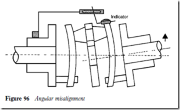
Test for angular misalignment
1 Mount the indicator on the left hand flange as shown in Figure 96, with the stem on the face of the right hand flange.
2 Rotate the equipment, notion the maximum and minimum indicator readings.
3 Move the equipment as necessary to reduce the total indicator reading to 0.0508 mm (0.002 in) or less for each millimetre (inch) of diameter at the indicator stem.
Test for parallel misalignment
1 Set the indicator on the outer surface of the flange as shown in Figure 97.
2 Rotate the equipment, noting maximum and minimum readings.
3 Move the equipment as necessary to reduce indicator readings to a minimum, taking care not to disturb the setting made in step 1.
4 The coupling should be rotated several complete revolutions to make sure that no endwise creep in the connected shafts is measured.
5 Tighten all bolts. Recheck tightness after several hours operation.
