Balancing Valves,Valve Adapters, and Filters
Hot-water heating and cooling systems often require additional balancing not foreseen in the preliminary planning. An effective method of balancing a heating or cooling system is to install balancing valves, valve adapter units, or balancing fittings at suitable locations in the pipelines in order to regulate water flow through the radiators, convectors, baseboard panels, radiant coils, return mains, and branches.
A balancing valve is a control device that functions as a combi- nation balancing, indicating, and shutoff valve. This valve is used
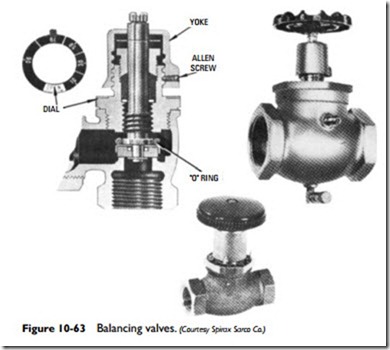
to balance a hot-water heating or cooling system and at the same time indicate the percent of flow through the valve. An example of one of these balancing valves is shown in Figure 10-63.
These valves are available in many body patterns and connection types, the selection depending on the requirements of the installation. Among the body patterns available are angle, angle union, globe, and globe union. The different connections include screwed, sweat, male, or female unions.
The balancing valve shown in Figure 10-63 is fitted with a balancing yoke that fits over the bonnet. The stem has a stop washer that shoulders on the balancing yoke. The yoke is rotated until the indicator on the calibrated dial points to the percent of flow required at a particular setting. At this point, it is locked in place with an Allen setscrew. The valve can then be opened until the stop washer contacts the top of the yoke, thereby permitting correct percentage of flow. For service work, the valve can be shut and, when opened, will never open beyond its set point. In addition, the valve is equipped with an O-ring that seals off against the bonnet to form a positive back seat, and the valve can be repacked under full line pressure.
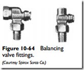
Balanced fittings, such as the ones shown in Figure 10-64, are used for balancing branch or circuit resistance of radiators, convectors,
heating or cooling coils, unit heaters, and other heat-transfer equipment employing hot or chilled water. Some are available with an integral manual air vent. They can also be obtained with a thread connection or with a sweat connection for nominal copper tube. When a balancing fitting is used, a stop valve must be installed with it to allow shutdown for necessary service.
Valve adapters are devices used to convert copper, bronze, cast brass, or cast-iron tees to balancing valves. These adapter devices can be threaded into cast-iron tees, or soldered or sweat-fitted into copper, bronze, or brass tees. They can also be inserted in a side outlet or run of tee of the same size to complete either a straightway or angle balancing valve. Because there is no inside reduction of
pipe diameter, there is no water restriction except for the balancing required. Balancing is accomplished by using a screwdriver on the adjustment screw at the top of the adapter device.
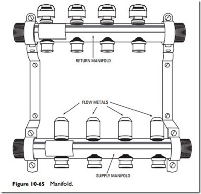
A manifold (sometimes called a zone manifold) is a device used to connect multiple tubing lines to a single supply or return line in a hydronic radiant floor heating system (see Figure 10-65). Each heating system has at least two manifolds: a supply manifold and a return manifold. A supply manifold receives water from the boiler through a single supply pipe and then distributes it through a number of different tubing lines to the rooms and spaces in the structure. A return manifold provides the opposite function. It receives the return water from each of the rooms and spaces through as many tubing lines and sends it back to the boiler by a single return pipe. A supply manifold and a return manifold are sometimes referred to jointly as a manifold station. Manifolds are described in greater detail in Chapter 1 (Radiant Heating)”in V olume 2.


