Compressor cascade performance
Within compressor blades, the flow is moving from a low static pressure at inlet toward a higher static pressure at exit. The fundamental difficulty in compressors is getting the flow to negotiate this pressure rise without generating high loss or separating. The axial compressor designer must choose an appropriate level of blade loading, such that the flow can achieve the required pressure rise, while not overdesigning the compressor, such that there are too many blades. In addition, compressors are required to perform satisfactorily over a range of operating conditions and the designer must produce a blade geometry that can tolerate variations in the operating point.
This section describes the key phenomena present in compressor cascades that determine their design and performance. It also presents some research into the aerodynamics of compressor blades and the correlations that these past studies have established.
Compressor loss and blade loading
Many experimental investigations have confirmed that the efficient performance of compressor cascade blades is limited by the growth and separation of the blade surface boundary layers. One of the aims of cascade research is to establish the generalized loss characteristics and stall limits of conventional blades. This task is made difficult because of the large number of factors that can influence the growth of the blade surface boundary layers, including surface velocity distribution, blade Reynolds number, inlet Mach number, free-stream turbulence and unsteadiness, and surface roughness. However, the analysis of experimental data have led to several correlation methods that enable the first-order behavior of the blade losses and fluid deflection to be predicted with sufficient accuracy for many engineering purposes.
The correlations of Lieblein (1959) and Johnson and Bullock (1965) are based on observations that high levels of velocity diffusion on the surfaces of compressor blades tend to produce thick boundary layers and eventual flow separation. Lieblein showed that in the region of minimum loss, the wake thickness and consequently the loss in total pressure are primarily related to the diffusion in velocity on the suction surface of the blade. He reasoned that the boundary layer on the suction surface of conventional compressor blades contributes the largest share of the blade wake, and, therefore, the suction-surface velocity distribution becomes the main factor in determining the total pressure loss.
A typical velocity distribution is shown in Figure 3.13 derived from surface pressure measurements on a compressor cascade blade operating in the region of minimum loss. From this it is clear that the fall in velocity on the suction surface is high and much greater than the overall
Since the local diffusion factor was relatively hard to determine, Lieblein, Schwenk, and Broderick (1953) developed the much used diffusion factor (DF) based on a theoretical surface velocity distribution similar to those actually measured on the NACA 65 Series and the British C4 Series cascades. This parameter requires knowledge of only the inlet and exit velocities from the blade and the pitch-chord ratio and is therefore very useful for preliminary design purposes:
The first term on the right-hand side, 1 2 c2/c1, represents the mean deceleration of the flow. The second term, (cθ1 2 cθ2)/2c1, represents the flow turning. The pitch-chord ratio, s/l, is important as this determines how well the flow is guided by the blades. A low value implies lower pres- sure gradients across the blade passages required to turn the flow and, hence, less diffusion. Lieblein showed that the loss in a blade row increases rapidly as the flow starts to separate, which occurs when the diffusion factor exceeds about 0.6. Typically, a well-designed blade with moderate loading will operate with a diffusion factor around 0.45. Although it was developed using just a small range of compressor blade designs operating at a minimum loss condition, the diffusion factor is widely applied to a range of compressor designs, both compressible and incompressible, for preliminary design purposes.
Another, even simpler, measure of the overall amount of diffusion through a compressor blade row is known as the De Haller number, c2/c1. This parameter, first proposed in De Haller (1953), is still often used to limit the maximum pressure rise across a compressor blade row. De Haller’s rule recommends that:
Fluid deviation
The flow leaving a compressor blade does not follow the blade camber line at the trailing edge. This deviation arises partly because the flow is diffusing within the blade passages. This means that the streamlines are diverging and therefore the flow is not moving in a single direction. This effect is exacerbated by the spacing of the blades because the flow is guided less by the blades when they are further apart. The deviation is further increased by viscous effects since any boundary layer growth on the blade surfaces will generate a blockage that modifies the effective blade shape.
Howell (1945a, b) and Carter (1950) developed an empirical relationship between the nominal deviation, δ*, occurring at the nominal (design) incidence angle i*, and the blade geometry:
where n 0.5 for compressor cascades and n � 1 for compressor inlet guide vanes (these can be considered as turbine blades because they accelerate the flow). Equation (3.34) is now widely referred to as Carter’s rule. It demonstrates that the deviation increases with pitch-chord ratio and blade camber. The value of m depends upon the precise shape of the camber line and the blade stagger. A typical correlation for m in a compressor cascade is
where the maximum camber of the blade is at distance a from the leading edge.
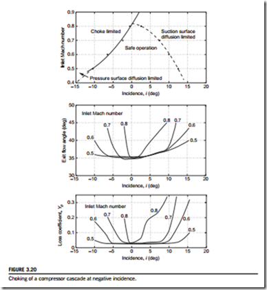
Deviation increases further as the incidence changes from the nominal condition and any flow separation will cause a rapid increase in deviation. An example of the detailed variation of exit angle with incidence and inlet Mach number is shown later, in Figure 3.20.
EXAMPLE 3.1
At its design operating point, a cascade has an inlet flow velocity of 150 m/s at an angle of 50o and an exit flow velocity of 114 m/s at an angle of 30o. Calculate the diffusion factor, DF, and the De Haller number if the pitch/chord ratio is 0.85. If the blade has a circular arc camber line and operates with 3o of incidence, find the deviation and the blade camber using Carter’s rule.
Solution
Incidence effects
Figure 3.14 shows a schematic of the flow around a compressor blade for different incidence conditions as well as the corresponding surface velocity distributions for a compressor cascade. At the design point of a compressor blade, the inlet flow angle is almost parallel to the camber line at the leading edge (i.e., the inlet blade angle). Hence, there is close to zero incidence and the surface pressure distribution for the blade should be smooth and continuous. In this case, almost all the deflection, or turning, of the flow is achieved via the camber of the blades. As the incidence is increased, the flow impinges on the blade pressure surface, and the flow on the suction surface must rapidly accelerate around the leading edge then decelerate to a speed comparable with the mainstream flow. This leads to very high local diffusion close to the front of the blade and sometimes what is referred to as a leading edge spike on the blade suction surface. The diffusion can cause boundary layer transition and, thus, higher blade losses, and at very high incidences the flow will separate, leading to stall. With positive incidence, the blade loading is higher and the flow deflection increased. Some of the turning can be thought of as being due to the blade camber, and some due to the incidence. At negative incidence, the flow accelerates around the leading edge onto the pressure surface. The pressure distributions on the front of the suction and pressure surfaces swap and the diffusion on the pressure surface is increased. The flow deflection is reduced and the loading is low. At very high values of negative incidence, the diffusion becomes so high that the flow can separate on the pressure surface.
The tolerance of the compressor blades to incidence variations is critical to enable stable and efficient off-design operation of a compressor. When a compressor operates at mass flow rates or rotational speeds that are away from the design point, the blades will be subject to incidence variations, as detailed in Chapter 5. Typically, a compressor blade needs to tolerate at least 6 5o variation of incidence without stalling, although the exact requirements will depend on the
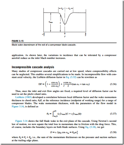
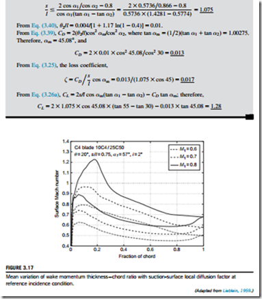
where DFloc is as defined in Eq. (3.31). Equations (3.39) and (3.40) provide a simple relationship between the blade stagnation pressure loss coefficient and the suction-surface velocity distribution. Note that the practical limit of efficient operation corresponds to a local diffusion factor of around 0.5.
EXAMPLE 3.2
A low-speed compressor cascade is to be tested with a flow inlet angle, α1 5 55o, and a flow exit angle, α2 5 30o. The expected design value of the local diffusion ratio, DFloc, is 0.4. Find a safe value for the pitch-chord ratio if the maximum value of the diffusion factor, DF, is assumed to be 0.6. Using Eqs (3.26), (3.39), and (3.40), determine values for ζ, CD, and CL.
Solution
Effects of Mach number
When flow velocities through a cascade are such that Mach numbers are above 0.3, the flow can no longer be treated as incompressible. The peak Mach number on the surface of a conventional compressor blade is significantly higher than the inlet Mach number. If the inlet Mach number exceeds about 0.7, the flow over the blade will become transonic, leading to performance deterioration. Figure 3.18 shows the surface Mach number distribution around a compressor aerofoil in a cascade at low incidence for different levels of inlet Mach number. Once the local Mach number on the suction surface exceeds 1, additional losses arise due to the presence of shock waves. In addition, the rapid pressure rise across the shock waves leads to thicker boundary layers and there- fore greater viscous losses. The higher diffusion on the suction surface at high inlet Mach number means that the blade boundary layers are likely to separate at modest levels of positive incidence.
In practice, the effects of high inlet Mach numbers are alleviated by using very thin blades and low camber. These features help to make the peak suction-surface Mach number not much higher than the inlet Mach number. As shown in Chapter 5, such blades can be used for highly efficient transonic compressor rotors with relative inlet Mach numbers up to 1.5.
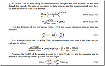
Figure 3.19 is a diagram showing the mean-line flow through a high-speed compressor cascade. For any cascade, given the inlet angle, α1, the inlet Mach number, M1, and the exit Mach number, M2, it is possible to calculate the exit angle, and thus the deviation, if the cascade loss coefficient,
Combining Eqs (3.41) and (3.42) gives the exit angle in terms of the inlet conditions, the loss coefficient, and the exit Mach number. Equally, the preceding expression can be used to find the exit Mach number or the loss coefficient in terms of the other quantities.
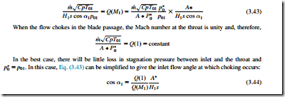
The effect of negative incidence at a high inlet Mach number can be demonstrated using an analysis similar to that presented previously to find when a compressor cascade will choke. Consider a compressor cascade with a minimum flow area, A*, as pictured in Figure 3.20. This minimum flow area is usually referred to as the throat of the blade passage. Applying conservation of mass between the inlet and the throat,
All the terms on the right-hand side of Eq. (3.44) are constant except Q(M1). This equation shows that, as the inlet Mach number increases, the cosine of the inlet angle when choking occurs decreases (and thus the actual angle increases). Therefore, the amount of negative incidence possible before choking occurs is reduced as the inlet Mach number increases. To avoid choking either the inlet angle must be increased or the inlet Mach number reduced.


